Power system
A power generation system and power generation unit technology, applied in the field of flow path structure, can solve the problem of combustible gas contained in combustion exhaust
- Summary
- Abstract
- Description
- Claims
- Application Information
AI Technical Summary
Problems solved by technology
Method used
Image

Examples
Embodiment approach 1
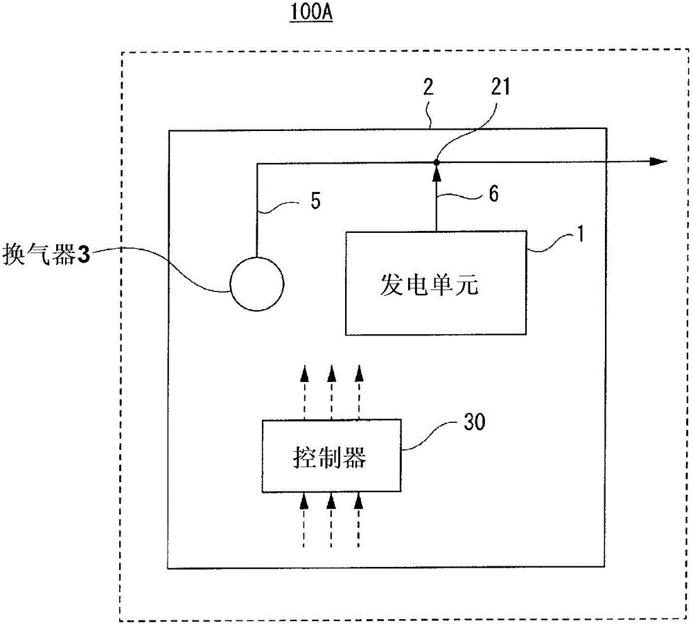
[0027] The power generation system according to Embodiment 1 includes: a power generation unit; a case for accommodating the power generation unit; a ventilator for ventilating the inside of the case; a gas flow path; and a second gas flow path provided in the casing, in which combustion exhaust gas from the power generation unit flows, wherein the second gas flow path joins the first gas flow path in the casing.
[0028] In a power plant, combustible gas may be contained in combustion exhaust gas. As such a case, for example, a case where incomplete combustion occurs in a power generating unit, etc. are mentioned. In this case, if the ventilation fan and the exhaust gas of the fuel cell are separately exhausted from the casing, the combustible gas in the combustion exhaust gas is discharged outside the casing without being diluted. However, according to the above configuration, the combustion exhaust gas of the power generation unit is mixed with the atmosphere (atmosphere) ...
Deformed example 1
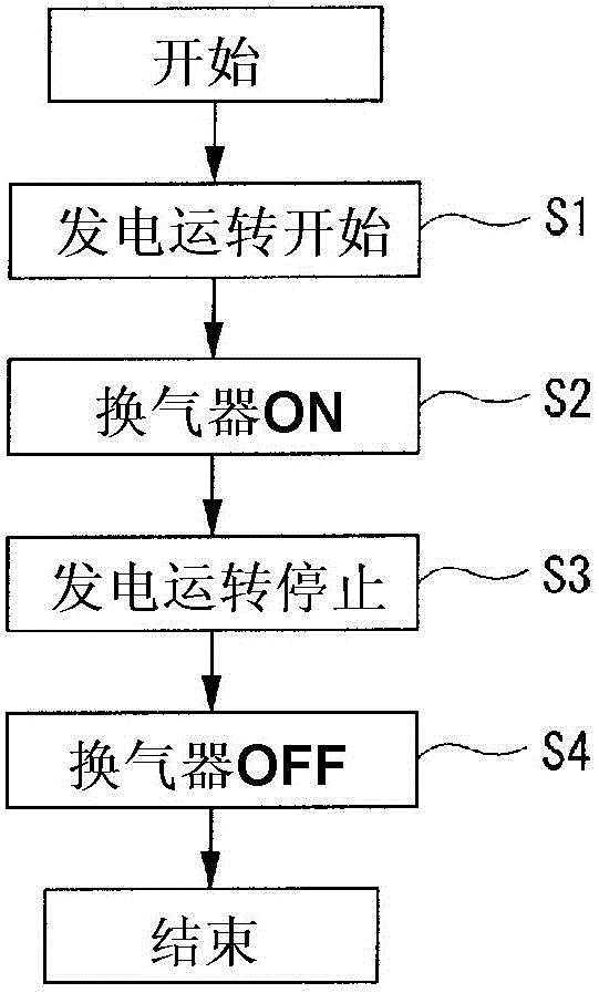
[0046] The power generation system according to Modification 1 may include a controller which, when the power generation system is stopped, continues the operation of the rebreather at least until discharge of combustion exhaust gas from the power generation unit stops.
[0047] According to the above configuration, the combustion exhaust gas is mixed with the atmospheric gas in the case by the operation of the rebreather until the discharge of the combustion exhaust gas from the power generation unit is stopped. When the combustion exhaust gas contains combustible gas, the combustion The combustible gas in the exhaust gas is diluted and discharged out of the casing.
[0048] Next, Modification 1 of the power generation system 100A of Embodiment 1 will be specifically described.
[0049] Figure 3A It is a flowchart showing the control of the controller in Modification 1 of the power generation system 100A of 1. Such as Figure 3A As shown, the controller 30 stops the power...
Deformed example 2
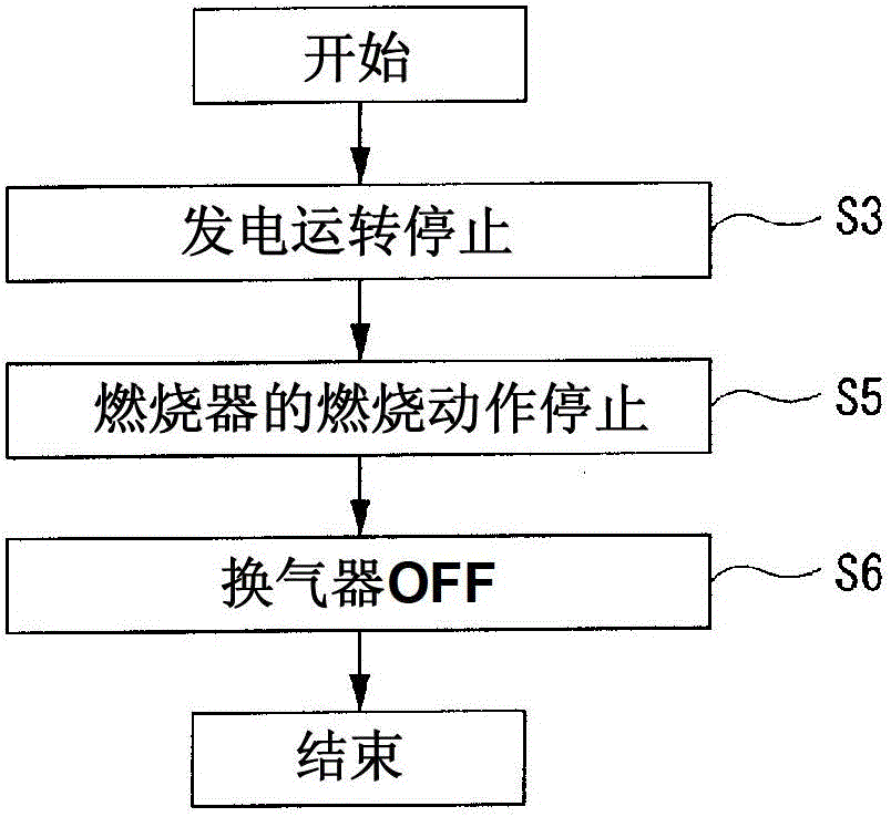
[0057] The power generation system of Modification 2 may include, in the power generation system of Embodiment 1, a controller which, when the power generation system is stopped, continues the operation of the ventilator at least until exhaust of the combustion exhaust from the power generation unit stops.
[0058] According to the above configuration, even if combustible gas is contained in the gas remaining in the discharge gas flow path after the discharge of the combustion exhaust gas from the power generation unit is stopped, the combustible gas is diluted by the atmospheric gas in the casing and discharged.
[0059] Next, Modification 2 of the power generation system 100A of Embodiment 1 will be specifically described.
[0060] Figure 3B It is a flowchart showing the control of the controller in Modification 2 of the power generation system 100A of 1. Such as Figure 3B As shown, the controller 30 stops the power generation operation of the power generation system 100...
PUM
 Abstract
Description
Claims
Application Information
 - R&D
- Intellectual Property
- Life Sciences
- Materials
- Tech Scout
- Unparalleled Data Quality
- Higher Quality Content
- 60% Fewer Hallucinations
Browse by: Latest US Patents, China's latest patents, Technical Efficacy Thesaurus, Application Domain, Technology Topic, Popular Technical Reports.
© 2025 PatSnap. All rights reserved.Legal|Privacy policy|Modern Slavery Act Transparency Statement|Sitemap|About US| Contact US: help@patsnap.com