
Blow molding panel and folding table applying same

A technology of blow molding panels and folding tables, which is applied in the field of folding tables, which can solve the problems of low structural strength of the panels, unsightly back of the panels, and bulky blow molding tables, etc., and achieve novel structures, ensure rigidity and strength, and reduce production costs Effect

Active Publication Date: 2013-08-14
蒋一翔
View PDF6 Cites 3 Cited by
  • Summary
  • Abstract
  • Description
  • Claims
  • Application Information

AI Technical Summary

Problems solved by technology

[0003] Taking the blow molding table as an example, it is usually made of a blow molding panel and a foldable iron bracket. The existing blow molding table often uses such a blow molding panel, which is distributed at the bottom of the blow molding panel There are many concave support points, but because the support points are arranged in parallel at the bottom of the blow-molded panel, it is easy to twist in the direction along which the support points are arranged in parallel, so that the structural strength of the panel is not high
In order to improve the structural strength, people have improved the distribution structure of the above-mentioned concave support contact points. For example, at the bottom of the blow-molded panel, there are many support contact points that are arranged randomly and have different shapes and sizes. The structural strength of the blown panel has a certain effect, but there is still room for further improvement in the structural strength, and this invisible arrangement also makes the back of the panel look unattractive
[0004] In addition, people also increase the structural strength of the blow-molded panel by increasing the thickness of the blow-molded panel. However, the defect of using a thickened panel is that the panel looks thicker. Not only more bulky, but also beneficial to save costs

Method used


Image

  • Blow molding panel and folding table applying same
  • Blow molding panel and folding table applying same
  • Blow molding panel and folding table applying same

Examples


Embodiment Construction

[0024] The present invention will be further described in detail below in conjunction with the accompanying drawings and embodiments.

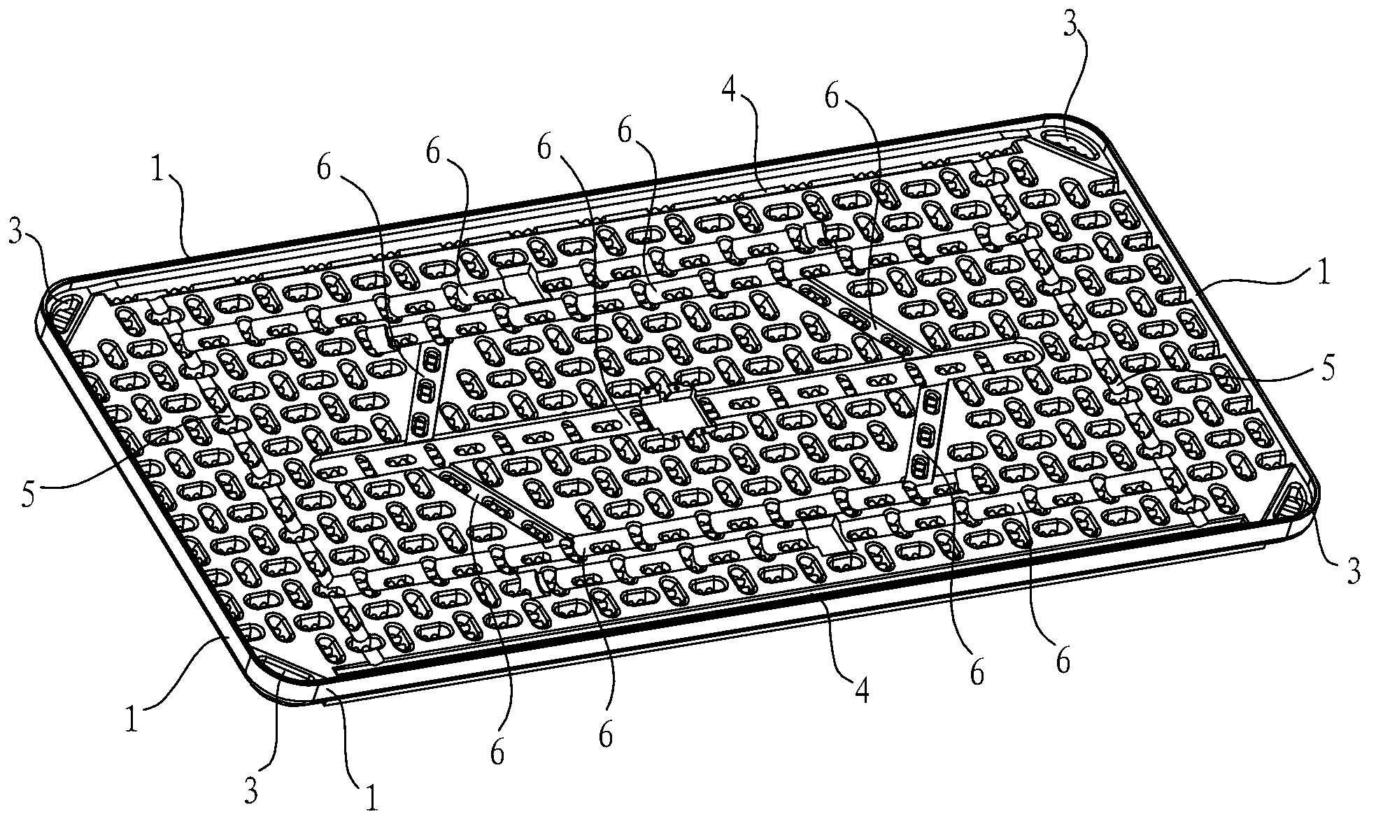
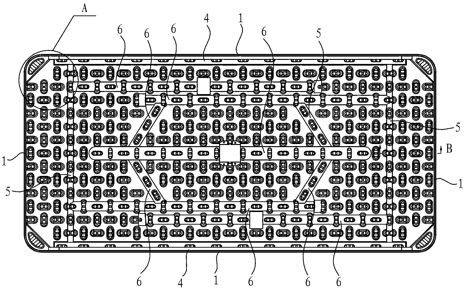
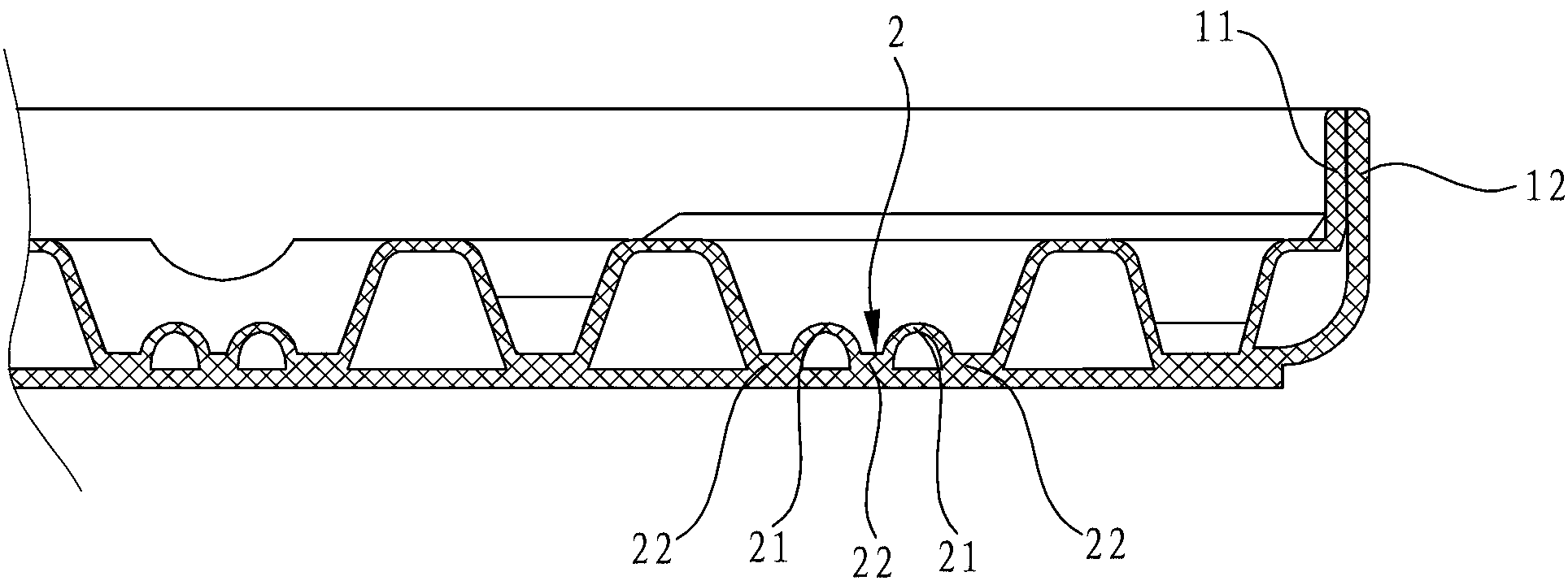
[0025] Such as Figure 1 to Figure 4 As shown, the blow-molded panel in this embodiment is distributed with many depressions on the back and is arranged in a vertical and horizontal staggered manner. The support contact points 2 are in the shape of strips. The external stress in one direction is decomposed into forces that are mutually involved in multiple directions, thereby enhancing the structural strength and twist resistance of the panel itself, and, after adopting the recessed support contact point 2, the wall thickness of the blow-molded panel can be reduced, Reduce the weight of the panel. Especially for ultra-thin (thickness<40MM) boards, after adopting criss-cross support contact points 2, its firmness can be greatly strengthened, making it difficult to deform. In addition, in order to improve the structural strength of the contact...


PUM


Abstract

The invention discloses a blow molding panel. A plurality of recessed support touch points are distributed at the back of the panel. The blow molding panel is characterized in that the support touch points are distributed in a crisscross manner. The invention further discloses a folding table applying the panel. Compared with the prior art, the folding table has the advantages that firstly, the hollow blow molding panel is novel in structure by the aid of the crisscross support touch points arranged at the back of the panel, the rigidity and the strength of the panel can be ensured while the panel is quite thin, production cost is reduced, secondly, a foot stool is conveniently and firmly mounted by the aid of a first slot, a second slot and an elongated groove which are arranged at the back of the panel, the panel and the foot stool can keep fine evenness after being completely folded, and a plurality of folding tables are more easily stacked after folded.

Description

technical field [0001] The invention relates to a panel and a folding table using the panel, in particular to a blow molding panel and a folding table using the blow molding panel. Background technique [0002] Blow molding products are light in weight due to their hollow structure. In addition, due to their material, shape and structure, they have the advantages of strong rigidity, good impact resistance, and not easy to damage. In recent years, blow molding products have been widely used in many fields. use. For example, there are various blow molding tables, blow molding chairs, blow molding stools, etc. in outdoor furniture products. [0003] Taking the blow molding table as an example, it is usually made of a blow molding panel and a foldable iron bracket. The existing blow molding table often uses such a blow molding panel, which is distributed at the bottom of the blow molding panel There are many concave support points, but because the support points are arranged i...

Claims


Application Information

Patent Timeline
IPC IPC(8): A47B96/20A47B3/091
CPCA47B13/08A47B3/0911B29C49/0031B29C49/04B29L2007/002
Inventor 蒋一翔
Owner 蒋一翔
Learn More