
Automobile air-knife window wiper

A wiper and air knife technology, applied in the field of automotive air knife wipers, can solve the problems of accelerated scraper wear, large frictional resistance between the scraper and the windshield, affecting the driver's sight, etc., and achieves the effect of increasing the speed.

Inactive Publication Date: 2013-08-14
黄建军
View PDF0 Cites 3 Cited by
  • Summary
  • Abstract
  • Description
  • Claims
  • Application Information

AI Technical Summary

Problems solved by technology

Because the scraper is tightly pressed against the windshield, the frictional resistance between the scraper and the windshield is relatively large, which accelerates the wear of the scraper on the one hand, and limits the movement speed of the scraper on the other hand. When the rain is heavy, it cannot be removed in time. Affect the driver's sight

Method used


Image

  • Automobile air-knife window wiper
  • Automobile air-knife window wiper

Examples


Embodiment Construction

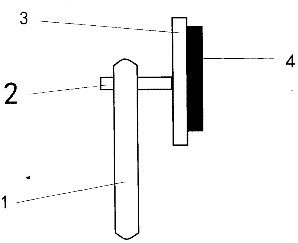
[0012] Such as figure 1 As shown, this is a traditional rubber wiper. The rubber strip 4 is clamped by a clamping plate 3, and the clamping plate 3 is connected to the rocker arm 1 through a rotating shaft 2. Under the action of the transmission mechanism, the rocker arm 1 drives the splint 3 to swing left and right, and the rubber strip 4 scrapes the rain and dust on the windshield.

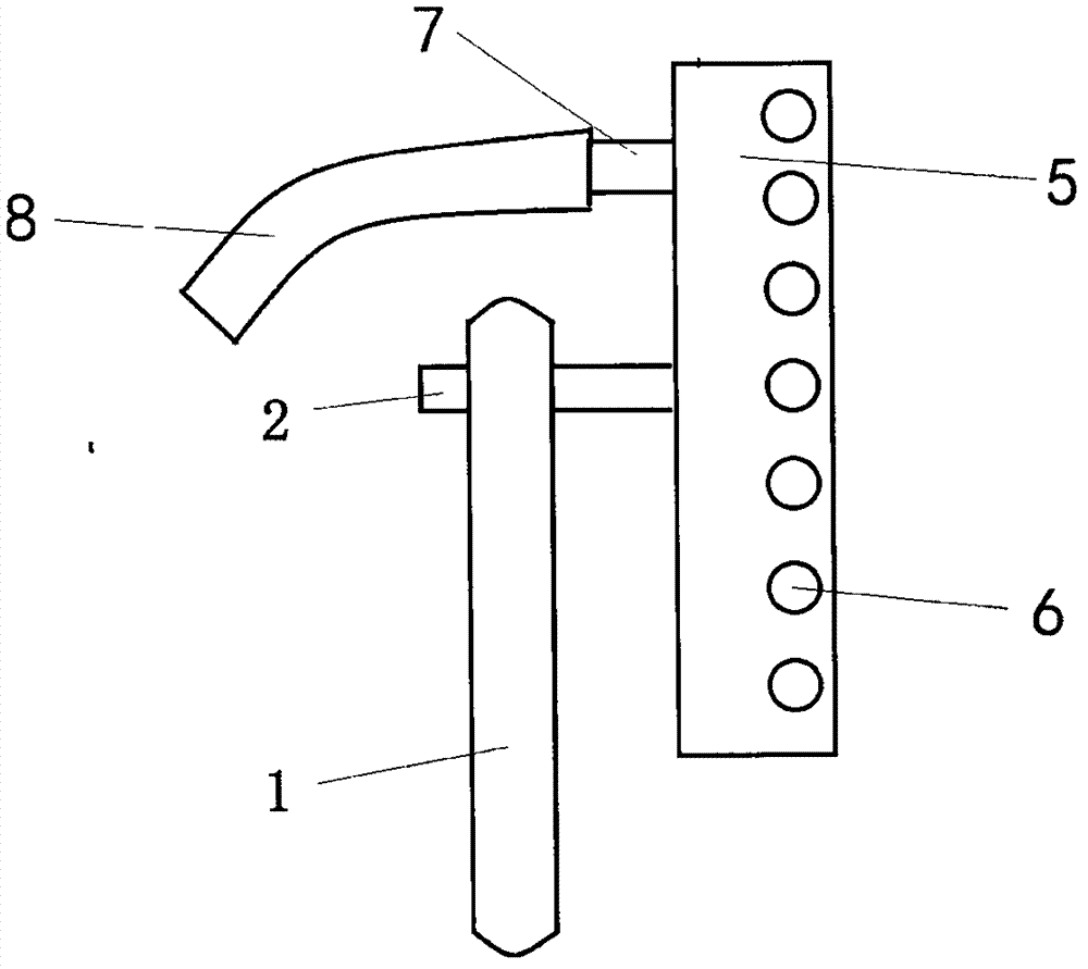
[0013] Such as figure 2 As shown, this is an air knife wiper. The air knife 5 is a tube with a discharge hole. The air knife 5 has an air outlet 6 and an air inlet 7, and the air inlet 7 is connected with the connecting pipe 8. When rain and dust on the windshield need to be wiped off, the air compressor is started, high-pressure air flows into the air knife 5 through the connecting pipe 8, and the high-pressure air is blown toward the windshield through the air outlet 6.


PUM


Abstract

An automobile air-knife window wiper comprises a wiper and a swing arm, and is characterized in that the wiper is composed of an air knife which is a tube with a row of gas outlets. Dust and rain on a windshield can be blown away by high-pressure gas blown out from the gas outlets.

Description

Technical field [0001] The invention belongs to the field of auto parts, in particular to an automobile air knife wiper. technical background [0002] In order to remove dust and rain from the front windshield of the car, every car is equipped with a wiper. The traditional wiper is composed of a scraper and a rocker arm, which is connected with a transmission mechanism. The scraper consists of a rubber strip and a splint. The swing arm swings left and right to drive the scraper to slide on the windshield, and the scraper scrapes the dust on the windshield. In order to ensure that the scraper reliably removes the dust on the windshield, the scraper must be tightly pressed on the windshield. Because the scraper is tightly pressed on the windshield, the frictional resistance between the scraper and the windshield is relatively large. On the one hand, it accelerates the wear of the scraper, and on the other hand, it limits the movement speed of the scraper. When the rain is heavy,...

Claims


Application Information

Patent Timeline
Patent Type & Authority Applications(China)
IPC IPC(8): B60S1/54
Inventor 黄建军
Owner 黄建军
Learn More