
Crude oil dissolved gas underground collecting apparatus

A collection device and dissolved gas technology, applied in wellbore/well components, production fluids, earth-moving drilling, etc., can solve the problems of reducing pump efficiency, being vulnerable to human damage, affecting well cleaning operations, etc., to reduce air pollution, reduce The effect of wasting resources

Inactive Publication Date: 2013-08-14
CHINA PETROLEUM & CHEM CORP +1
View PDF15 Cites 2 Cited by
  • Summary
  • Abstract
  • Description
  • Claims
  • Application Information

AI Technical Summary

Problems solved by technology

[0008] The purpose of the present invention is to provide a crude oil dissolved gas downhole collection device, which solves the problems that the current domestic dissolved gas collection device will reduce the pump efficiency, be easily damaged by human beings, affect the well cleaning operation and measure the dynamic liquid level, etc., without affecting the pumping Under the premise of oil well production and normal maintenance operations, the efficient and safe collection of dissolved gas is realized

Method used


Image

  • Crude oil dissolved gas underground collecting apparatus
  • Crude oil dissolved gas underground collecting apparatus
  • Crude oil dissolved gas underground collecting apparatus

Examples


Embodiment Construction

[0025] The detailed description and technical content of the present invention are described below with the accompanying drawings, but the accompanying drawings are only provided for reference and description, and are not intended to limit the present invention.

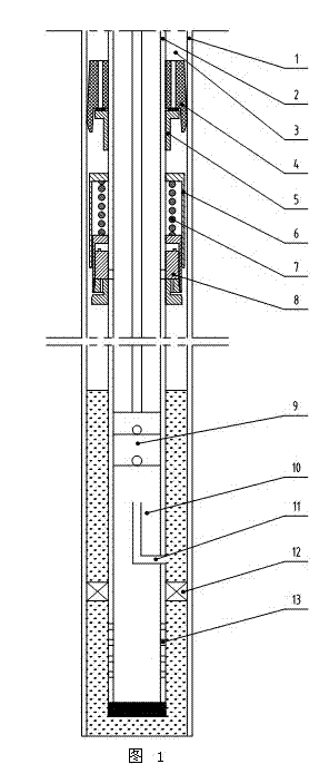
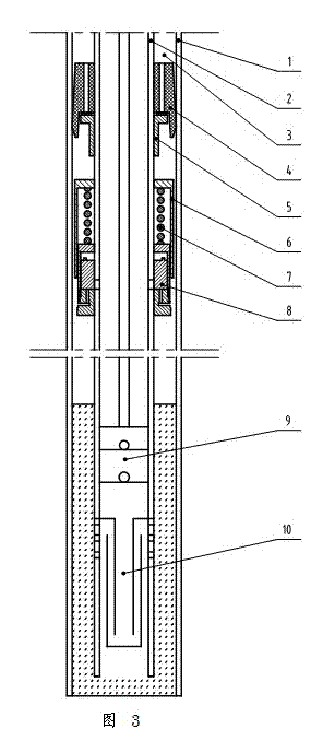
[0026] see figure 1 , crude oil dissolved gas downhole collection device, including the collection device under the crude oil dissolved gas pump installed below the oil well pump and / or the upper collection device installed on the crude oil dissolved gas pump above the oil well pump; The annular space formed between the casing and the oil pipe is the oil jacket annulus.

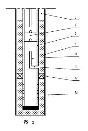
[0027] see figure 2 , is the down-pump collection device of the crude oil dissolved gas downhole collection device of the present invention, and the device mainly includes a gas-liquid separator 10, an oil jacket communication valve 11, a packer 12, a gas-liquid collector 13 and other components. A gas-liquid collector 13 is installed at the lowe...


PUM


Abstract

The invention provides a crude oil dissolved gas underground collecting apparatus. The crude oil dissolved gas underground collecting apparatus includes an above-pump collecting device and a below-pump collecting device which are used for collecting dissolved gas above a pump and below the pump respectively, and the appropriate collecting device is selected for different oil wells. According to the above-pump collecting device, the interspace of an oil lantern ring is sealed with a sealing rubber sleeve on the periphery of the opening of the well, and the gas is collected by entering an oil pipe through a one-way valve; when the well is cleaned, the sealing rubber sleeve shrinks inwards through high pressure flushing fluid and further moves downwards continuously to push a sealing cover to seal and close the one-way valve, the flushing fluid cannot pass through the one-way valve to enter the oil pipe, and accordingly the well cleaning is guaranteed to be carried out smoothly; and when the working fluid level is measured, the interspace of the oil lantern ring above the sealing rubber sleeve is pressed, and a float valve moves downwards to open an inner hole of the sealing rubber sleeve to further form a sound wave transmission channel. According to the below-pump collecting device, the of the oil lantern ring below the pump is sealed and closed through a packer, the gas is collected by entering the pump, and the fluid enters the interspace of the oil lantern ring through an oil sleeve communicating valve above the packer to form the working fluid level. Both the above pump collecting device and the below pump collecting device do not affect the routine maintenance of the well, such as well cleaning and fluid level measurement.

Description

technical field [0001] The invention relates to a technology for collecting dissolved gas in the crude oil production process of an oil field, in particular to a downhole collection device for crude oil dissolved gas. Background technique [0002] Crude oil contains a considerable amount of dissolved natural gas. During the extraction process, these dissolved gases will gradually volatilize in the form of gas to form free gas. Part of the free gas will be pumped out together with the well fluid, and the rest will be collected in the oil casing annulus. A large amount of dissolved gas stored in the casing will press the dynamic liquid level of the oil well and have a great impact on crude oil production. The traditional treatment method is to open the casing gate to discharge into the atmosphere, which not only causes waste of resources, but also causes serious pollution to the atmosphere. [0003] At present, there are many technologies for collecting dissolved gas from cr...

Claims


Application Information

Patent Timeline
IPC IPC(8): E21B43/00
Inventor 沈国华刘雨文马增海王亚洲段忠习徐宏国牛孝海
Owner CHINA PETROLEUM & CHEM CORP
Learn More