Method and device for testing flow conductivity of fracture network of shale

A technology of fracture network and flow conductivity, which is applied in the direction of earthwork drilling and production, wellbore/well components, etc., to achieve the effect of simple operation, economical and environmental protection, and low cost

Inactive Publication Date: 2013-08-14
CHANGZHOU UNIV
View PDF6 Cites 21 Cited by
  • Summary
  • Abstract
  • Description
  • Claims
  • Application Information

AI Technical Summary

Problems solved by technology

However, there is currently no test method and equipment for the influence of the fracture network formed by artificial fracturing in shale gas reservoirs on the conductivity

Method used


Image

  • Method and device for testing flow conductivity of fracture network of shale
  • Method and device for testing flow conductivity of fracture network of shale
  • Method and device for testing flow conductivity of fracture network of shale

Examples


Embodiment Construction

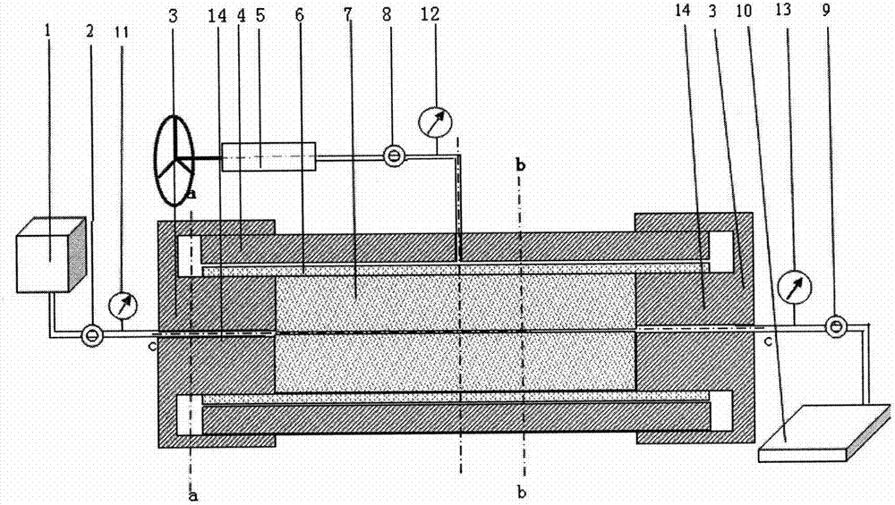
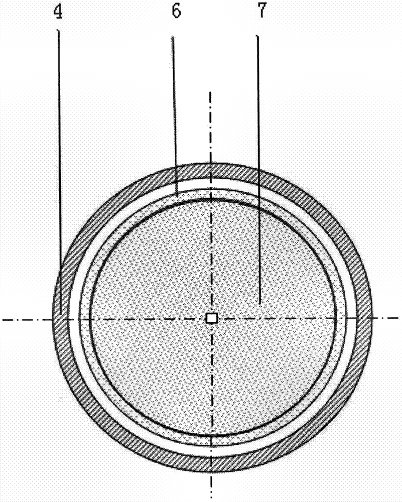
[0029] 1. Use the main components of the shale to be tested to make a semicircular model with a groove in the middle, and align and compress the two semicircular models to form a shale fracture network model 7 with a fracture network in the middle.

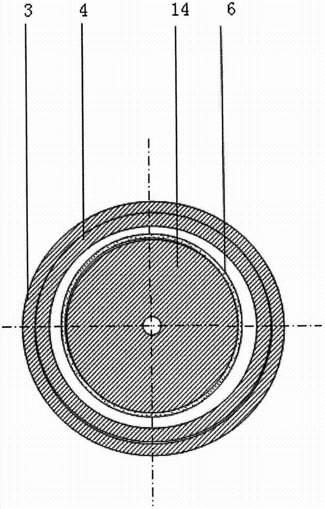
[0030] 2. Select the models of the annular sleeve 6 and the diversion chamber according to the size of the network model. Connect the selected diversion outer cylinder 4 with the ring pressure device 5 .

[0031] 3. Slowly push the shale fracture network model into the annular sleeve 6, then push the annular sleeve and the shale fracture network model 7 into the diversion chamber 4, and add a cover 3 at both ends of the diversion chamber to make the seal The cover inside projection 14 is inside the annular sleeve 6 and tightens the cover 3 .

[0032] 4. Open the ring pressure liquid supply valve 8, apply the ring pressure to the diversion chamber with the hand pump 5, and record the ring pressure with the ring pressure manometer ...


PUM


Abstract

The invention aims to provide a method and a device for testing the flow conductivity of a fracture network of shale. The device comprises a flow conducting chamber, an annular pressure loading device, a fluid supply device and a fluid measuring device. The device and the method for testing the flow conductivity of the fracture network of the shale have the advantage that the flow conductivity of volume fractures under a gas reservoir condition of the shale can be simulated.

Description

Technical field [0001] The technical field of the present invention is a test method and equipment for the influence of the fracture network formed by volume fracturing of shale gas reservoirs on the conductivity. Background technique [0002] The existing fracture conductivity test method can simulate the downhole pressure and temperature under standard experimental conditions to evaluate the conductivity of fracture proppant to different fracturing fluids, so as to compare the performance of various proppant fracturing fluids. The formula calculates the fracture width under each closure pressure and the influence of different proppants on the conductivity. During the exploitation of shale gas, hydraulic fracturing is used to reform the reservoir. While one or more main fractures are formed, secondary fractures will be formed laterally to the main fractures. Continue to branch to form secondary secondary fractures, and so on, forming a fracture network of natural fractures...

Claims


Application Information

Patent Timeline
Patent Type & Authority Applications(China)
IPC IPC(8): E21B49/00
Inventor 何岩峰卢强王烁龙田仁连陈宇星钟明
Owner CHANGZHOU UNIV
Why Eureka
Try Eureka