Bushing type air bearing and main shaft device

An air bearing, bushing technology, used in bearings, bearing cooling, bearing components, etc.

Active Publication Date: 2013-08-14
OFUNA TECH
View PDF9 Cites 10 Cited by
  • Summary
  • Abstract
  • Description
  • Claims
  • Application Information

AI Technical Summary

Problems solved by technology

However, the former increases the cost of equipment and operation, and the latter increases the cost of precisi...

Method used


Image

  • Bushing type air bearing and main shaft device
  • Bushing type air bearing and main shaft device
  • Bushing type air bearing and main shaft device

Examples


Embodiment Construction

[0030] The present invention will be described in detail below in conjunction with the accompanying drawings and embodiments.

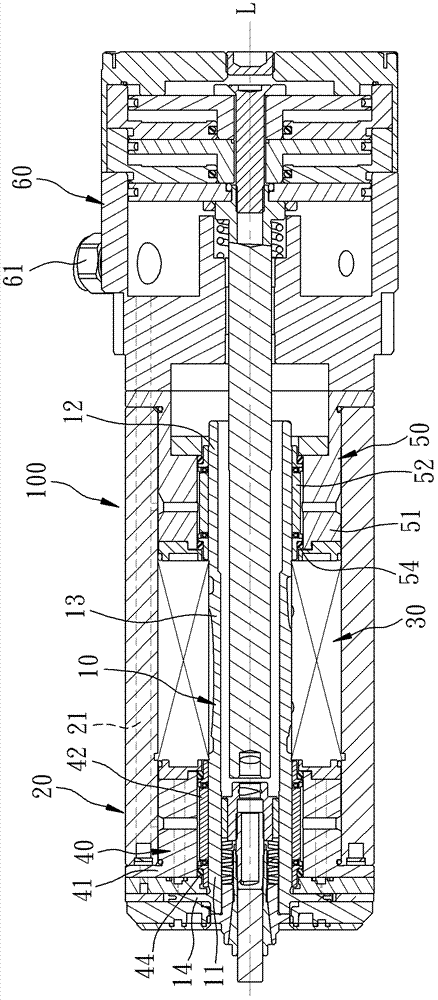
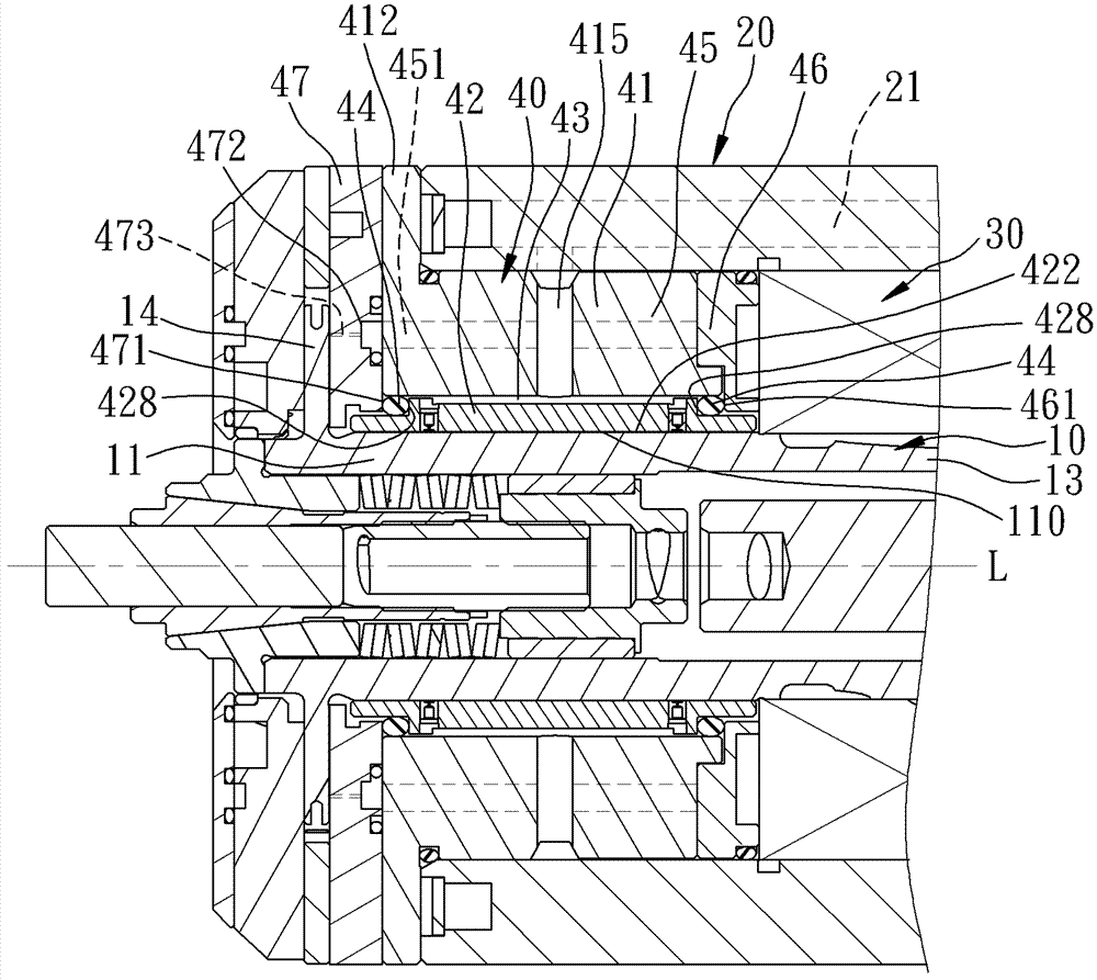
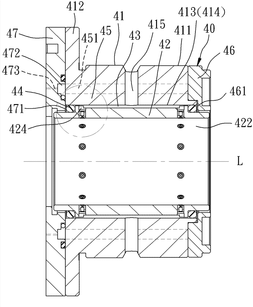
[0031] Such as figure 1 As shown, a preferred embodiment of the bushing air bearing of the present invention can be a front air bearing or a rear air bearing, and is suitable for being installed inside a spindle device 100, which includes a spindle unit 10, a sleeve The casing 20 arranged outside the spindle unit 10, a motor 30 sleeved between the spindle unit 10 and the casing 20, a front air bearing 40 arranged on the front side of the motor 30, a front air bearing arranged on the The rear air bearing 50 on the rear side of the motor 30 and a head unit 60 disposed on the rear side of the rear air bearing 50 .

[0032] The spindle unit 10 extends along an axis L, and has a front end 11, a rear end 12, a middle section 13 between the front end 11 and the rear end 12, and a 11 and a positioning disc member 14 extending radially.

[0033] The casing 20...


PUM


Abstract

The invention relates to a bushing type air bearing and a main shaft device. The air bearing comprises an outer ring seat, an inner bushing sleeved in the outer ring seat, an annular space disposed between the outer ring seat and the inner bushing, and two buffering leakproof rings respectively arranged between the outer ring seat and the inner bushing, wherein the outer ring seat is provided with at least one air-entraining hole; the inner bushing is provided with a plurality of gas ports capable of communicating with the air-entraining holes through the circular space; and the buffering leakproof rings can make the circular space isolated from an the outside world. Besides, the main shaft apparatus is provided with the air bearing. Thereby, the air bearing provides a mandrel unit stable support.

Description

technical field [0001] The invention relates to a processing machine, in particular to a bush type air bearing and a main shaft device. Background technique [0002] In order to meet the requirements of high-speed operation, the spindle unit has been supported by air bearings instead of ball bearings inside the spindle unit. Related patents such as EP1207315 and China Taiwan I230642, and the air bearings in these previous cases It is a one-piece structure, which is locked with the outer casing, and the outer casing is locked by the saddle of the machine tool, so it is difficult for the air bearing to generate high-frequency resonance with the spindle unit, which suppresses the maximum speed of the spindle unit. Currently, the industry There are two ways to try to increase the maximum speed. One is to increase the air pressure to about 0.7Mpa, and the other is to reduce the air gap between the air bearing and the spindle unit to about 20μm, and the above two methods can only ...

Claims


Application Information

Patent Timeline
IPC IPC(8): F16C32/06F16C37/00B23B19/02B23Q11/12
Inventor 丁志辉沈庆辉吴嘉达
Owner OFUNA TECH
Why Eureka
Try Eureka