Cold-rolled tin plate continuous annealing line temper mill roll shape configuration method and configuration structure

A configuration method and technology of annealing line, applied in the field of metallurgy, can solve the problems of reducing production time, shutdown replacement, uneven wear between rolls, etc., and achieve the goals of increasing average production speed, reducing rolling force pressure difference, and increasing service kilometers Effect

Pending Publication Date: 2022-03-08
SHAGANG GROUP +2
View PDF0 Cites 0 Cited by
  • Summary
  • Abstract
  • Description
  • Claims
  • Application Information

AI Technical Summary

Problems solved by technology

[0003] In actual production, the skin pass mill often has the problem of large rolling force difference (referred to as pressure difference) between the operating side and the driving side (OS-DS), which is difficult to control, mainly manifested in: (1) New backup rolls There is no large pressure difference when the machine is on the machine, but it appears after a certain period of production; (2) The pressure difference is irregular
[0004] Further analysis shows that the reason for the large pressure difference that is difficult to control is: (1) The temperature of the bearing ends on both sides of the work roll body is higher than that of the middle section during production, and the thermal expansion forms a negative convex hot roll shape. It is a flat roll shape, and the work roll is also similar to a flat roll shape (+20um), which cannot compensate for the influence of the negative crown hot roll shape; No cooling, no lubrication, very severe uneven wear at both ends of the roll body between the backup roll and the work roll
[0005] The problem of large pressure difference seriously affects the normal production. On the one hand, the pressure difference is occasionally too large to cause tripping, which affects the production of the whole line;
The problem of the large pressure difference of this skin pass mill comes from its dry skin pass process, which brings about complex production problems of uneven wear between rolls and thermal crown interference. The existing technology only adopts reduced speed production and increases the frequency of changing support rolls The way to avoid large quality fluctuations and sudden failures of production stoppages, which reduces the effective production time and increases product costs

Method used


Image

  • Cold-rolled tin plate continuous annealing line temper mill roll shape configuration method and configuration structure
  • Cold-rolled tin plate continuous annealing line temper mill roll shape configuration method and configuration structure
  • Cold-rolled tin plate continuous annealing line temper mill roll shape configuration method and configuration structure

Examples


Embodiment 1

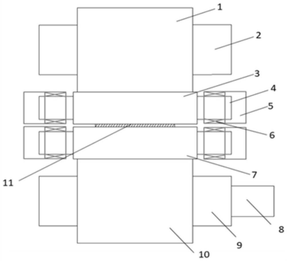
[0046] refer to Figure 1-12 , 13-07, TW044, TW073, and TW076 in the accompanying drawings of the specification are steel stamp numbers on the work rolls. The present invention provides a technical solution, a roll shape configuration method for a cold-rolled tin plate continuous annealing line tempering machine, including:

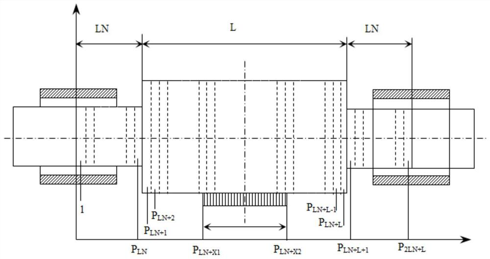
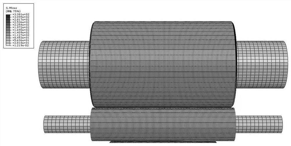
[0047] Step 1: Measure the temperature of each section of the work roll surface, regularly detect the hot and cold roll shapes of the off-line work rolls, combine the simulated annealing algorithm and the finite difference method, optimize and determine the parameters of the model with the measured data, and use the model Predict and calculate the hot roll shape of the work roll of the tempering machine of the tin plate continuous annealing unit, calculate the temperature change of each section of the roll surface at each stage of the work roll service period, predict the hot roll shape and the trend curve of the hot roll shape; the details are as follows:...

Embodiment 2

[0108] refer to Figure 1-12 13-07, TW044, TW073, and TW076 in the accompanying drawings of the specification are all steel stamp numbers on the work rolls. On the basis of Example 1, a roll shape configuration method for a cold-rolled tin plate continuous annealing line tempering machine includes:

[0109] Step 1: Use an infrared thermometer to continuously measure the temperature of each section of the work roll surface online, regularly use the Japanese Anritsu thermometer HA150K to measure the temperature of the work roll surface when the machine is off the machine, and use a saddle frame to detect the roll shape and shape of the off-line work roll. The cold roll shape, the difference between the hot roll shape and the cold roll shape is the measured hot roll shape, and the measurement results are shown in Figure 4 and Figure 5 . Using the combination of simulated annealing algorithm and finite difference method to model and predict the hot roll shape of the roll, opti...

Embodiment 3

[0126] refer to Figure 1-12 , the present invention provides a technical solution, on the basis of Example 1, a roll shape configuration structure of a cold-rolled tin plate continuous annealing line tempering machine, the work roll adopts the roll shape curve of the TCR work roll, and the back-up roll adopts the SBR back-up roll Roller curve.


PUM


Abstract

The invention discloses a cold-rolled tin plate continuous annealing line temper mill roll shape configuration method and configuration structure, and belongs to the technical field of metallurgy, and the method comprises the following steps: analyzing roll surface temperature distribution and hot roll shape in the service period of a working roll; designing a new working roll shape for compensating the hot roll shape; designing a new roll shape of the supporting roll, wherein the contact pressure between the supporting roll and the working roll is uniformly distributed; discretizing newly designed roll shape data, and inputting the discretized data into a grinding machine for grinding. The device is applied to a certain cold-rolled tin plate continuous annealing line temper mill, through the synchronous design of the TCR roller shape of the working roller and the SBR roller shape of the supporting roller, uniform abrasion between the supporting roller and the working roller is achieved, the rolling force pressure difference between the operation side and the transmission side is remarkably reduced, the high-speed operation stability of a unit is improved, and the average production speed is remarkably increased; the service kilometers of the supporting roller are increased by more than one time, and the production capacity of a tin plate continuous annealing line is remarkably improved.

Description

technical field [0001] The invention belongs to the technical field of metallurgy, and relates to a roll configuration method and a configuration structure of a cold-rolled tin plate continuous annealing line tempering machine. Background technique [0002] The tempering machine of the continuous annealing line of cold-rolled tin plate is an important equipment to ensure the quality of the finished tin plate. Controlling the roughness and brightness of the finished strip plays a very important role. [0003] In actual production, the skin pass mill often has the problem of large rolling force difference (referred to as pressure difference) between the operating side and the driving side (OS-DS), which is difficult to control, mainly manifested in: (1) New backup rolls There is no large pressure difference when the machine is on the machine, but it appears after a certain period of production; (2) The pressure difference is irregular. [0004] Further analysis shows that th...

Claims


Application Information

Patent Timeline
Patent Type & Authority Applications(China)
IPC IPC(8): B24B5/37B21D1/02B21D37/00G06F30/23
CPCB24B5/37B21D1/02B21D37/00G06F30/23
Inventor 孙林丁美良赵慧江关建辉杨丽琴
Owner SHAGANG GROUP
Why Eureka
Try Eureka