LED (Light Emitting Diode) lamp with multiple heat dissipation structures

A technology for LED lamps and multiple heat dissipation, applied in lighting and heating equipment, semiconductor devices of light-emitting elements, cooling/heating devices of lighting devices, etc., can solve problems such as poor air circulation, narrow heat dissipation space, and high cost of lamps , to achieve the effect of fast heat dissipation

Active Publication Date: 2013-08-14
黄超
View PDF5 Cites 1 Cited by
  • Summary
  • Abstract
  • Description
  • Claims
  • Application Information

AI Technical Summary

Problems solved by technology

[0002] With the development of economy and society and the continuous improvement of LED lighting technology, LED lighting fixtures have been more and more widely used in people's daily work and life. At present, LED high bay lights, flood lights, LED tunnel lights, The reflectors (reflectors, hoods) and power boxes and radiators of LED lamps such as LED floodlights all perform their own single functions respectively, and fail to make comprehensive use of them so that all components can fully play their composite roles, resulting in ugly appearance. The cumbersome lamps also make the cost of lamps high. The superposition of these many unfavorable factors prevents the advantages of low carbon and energy saving of LED lamps from being fully utilized, which limits the application of LEDs, especially for LED lamps. Specially configured radiators , because there is no combination of the overall structure of the LED lamp, but only rely on the radiator itself for heat dissipation, the traditional radiator often has a narrow cooling space and poor air circulation, and the material and production costs of the LED lamp are relatively high. In view of the above-mentioned problems and defects, It is necessary to propose new improvements to the design of existing LED lighting fixtures

Method used


Image

  • LED (Light Emitting Diode) lamp with multiple heat dissipation structures
  • LED (Light Emitting Diode) lamp with multiple heat dissipation structures
  • LED (Light Emitting Diode) lamp with multiple heat dissipation structures

Examples


Embodiment Construction

[0022] The present invention will be further described below in conjunction with the accompanying drawings.

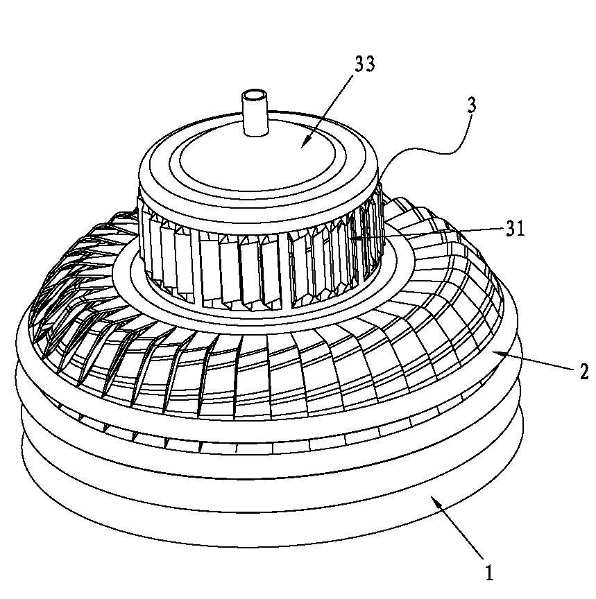
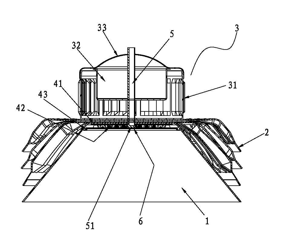
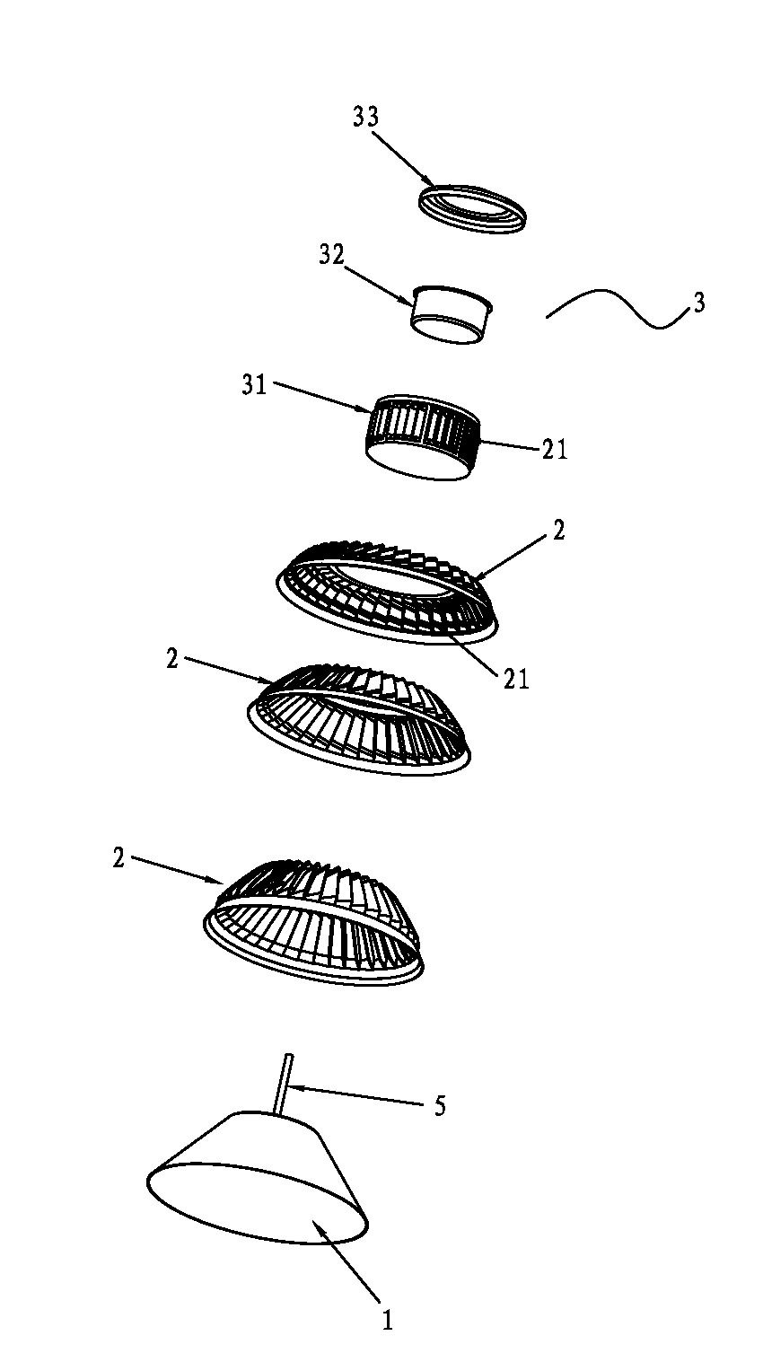
[0023] Such as figure 1 , figure 2 , image 3 , Figure 4 As shown, an LED lamp with multiple heat dissipation structures includes a lampshade 1, an LED lighting assembly, a cylindrical heat dissipation cover 2 with a lower opening, an LED power supply and a power supply box 3; the circumferential wall of the heat dissipation cover 2 has The heat dissipation guide hole 21; the LDE light-emitting component includes an aluminum substrate 41, an LED lamp bead 42 and a lens 43, the aluminum substrate 41 is fixed on the top plate of the lampshade 1, and the top plate of the heat dissipation cover 2 is bonded to the top plate of the lampshade 1; the heat dissipation cover There is a gap between the circumferential wall of 2 and the circumferential wall of lampshade 1,

[0024] The direction of the heat dissipation guide hole on the heat dissipation cover 2 is left-hande...


PUM


Abstract

An LED (Light Emitting Diode) lamp with multiple heat dissipation structures comprises a lamp shade, an LED light emitting assembly, a cylindrical heat dissipation cover with a lower opening, an LED power supply and a power supply box. The direction of a heat dissipation diversion hole which is formed on the cylindrical heat dissipation cover is levorotatory or dextrorotatory, one side of a cut gap which is arranged on the circumferential wall of the cylindrical heat dissipation cover is concaved inward towards the cylindrical heat dissipation cover, and the other side of the cut gap is concaved towards the outer side of the cylindrical heat dissipation cover to form into the heat dissipation diversion hole; the power supply box comprises an outer box with an upper opening, an inner box with an upper opening and a top cover; the circumferential wall of the outer box is provided with a heat dissipation diversion hole, one side of a cut gap which is arranged on the circumferential wall of the outer box is concaved inward towards the cylindrical heat dissipation cover, and the other side of the cut gap is concaved towards the outer side of the cylindrical heat dissipation cover to form into the heat dissipation diversion hole; and a base board of the outer box is closely attached to a top board of the cylindrical heat dissipation cover. According to the LED lamp with the multiple heat dissipation structures, an aluminum substrate transfers heat to the lamp shade to enable the lamp shade to directly perform heat dissipation and transfer part of the heat to the cylindrical heat dissipation cover; the heat dissipation diversion hole which is formed on the cylindrical heat dissipation cover enables the area of the heat dissipation not to be reduced and enables air to flow; and accordingly a rapid heat dissipation effect is achieved.

Description

technical field [0001] The invention relates to the technical field of LED lighting, in particular to an LED lamp with multiple heat dissipation structures. Background technique [0002] With the development of economy and society and the continuous improvement of LED lighting technology, LED lighting fixtures have been more and more widely used in people's daily work and life. At present, LED high bay lights, flood lights, LED tunnel lights, The reflectors (reflectors, hoods) and power boxes and radiators of LED lamps such as LED floodlights all perform their own single functions respectively, and fail to make comprehensive use of them so that all components can fully play their composite roles, resulting in an ugly appearance. The cumbersome lamps also make the cost of lamps high. The superposition of these many unfavorable factors prevents the advantages of low-carbon and energy-saving LED lamps from being fully utilized, which limits the application of LEDs, especially f...

Claims


Application Information

Patent Timeline
Patent Type & Authority Applications(China)
IPC IPC(8): F21S2/00F21V29/00F21Y101/02F21K9/237F21V29/83F21Y115/10
Inventor 黄超
Owner 黄超
Why Eureka
Try Eureka