

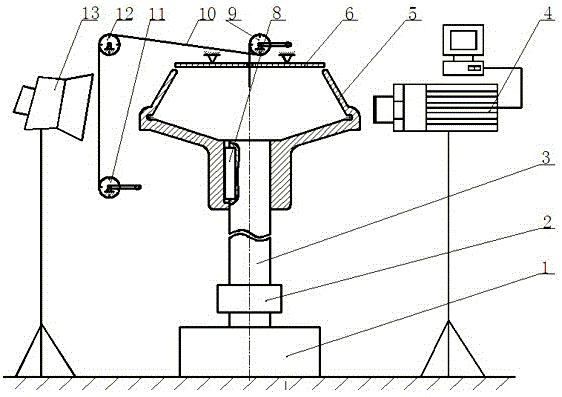
Measurement device for yarn movement in shear flow field in high-speed spinning cup
A motion measurement and internal shearing technology, which is applied to spinning machines, open-end spinning machines, and continuously wound spinning machines, etc., can solve the problem of poor identification of the local shape of the yarn and the difficulty in realizing the visual observation of the rotor. And other issues
- Summary
- Abstract
- Description
- Claims
- Application Information
AI Technical Summary
Problems solved by technology
Method used
Image

Examples
Embodiment Construction
[0017] The present invention will be further described below in conjunction with accompanying drawings and examples.
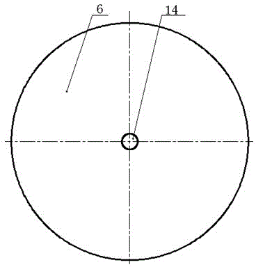
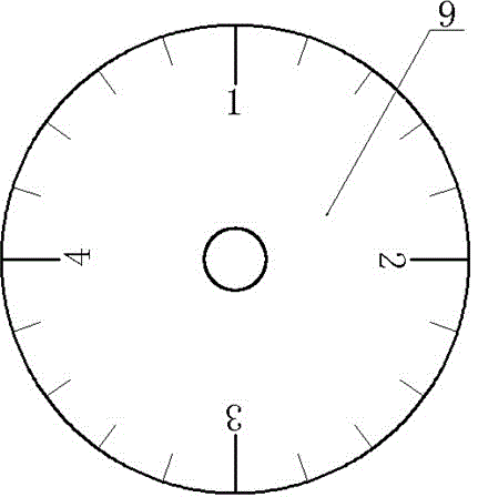
[0018] Such as figure 1 , figure 2 , image 3 , Figure 4 As shown, the present invention includes a motor 1, a shaft coupling 2, a rotating shaft 3, a high-speed camera 4, a rotor 5, a rotor cover 6, a key 8, a yarn delivery wheel 9, a yarn 10, a yarn storage wheel 11, and a support wheel 12. Lighting lamp 13 and yarn feeding hole 14; motor is fixed on the bottom surface, motor 1 is connected with one end of rotating shaft 3 through coupling 2, the other end of rotating shaft 3 is connected with rotor 5 through key 8, and rotor cover 6 is fixed on On the wall, and located at the upper end of the rotor 5, there is a yarn delivery hole 14 in the center of the rotor cover 6, a yarn delivery wheel 9 is installed directly above the center of the rotor cover 6, and a high-speed camera 4 is arranged on the outer side of the rotor 5, The high-speed camera 4 is f...
PUM
 Abstract
Description
Claims
Application Information