Vacuum infusion process and drainage tube used for vacuum infusion process

A technology of vacuum perfusion and diversion tube, which is applied in the field of diversion tube and vacuum perfusion technology, can solve problems such as not easy to clean, vacuum leakage, burnout of diversion tube and diversion net, etc., so as to facilitate recycling and prevent Vacuum leakage, avoiding the effect of material waste

Active Publication Date: 2013-08-21
XINJIANG GOLDWIND SCI & TECH
View PDF2 Cites 15 Cited by
  • Summary
  • Abstract
  • Description
  • Claims
  • Application Information

AI Technical Summary

Problems solved by technology

Currently, there is usually a large amount of resin remaining in the nozzle after the vacuum infusion process is completed, for example, for the blade shell and its components (e.g. main spar preform, web Plate prefabricated parts, root prefabricated parts, etc.) usually have a length of several hundred meters. For the forming process of a 59m single fan blade, it is necessary to use a total length of 600 meters to 700 meters. In this way, The residual resin in the draft tube is usually as much as 360kg to 420kg, which causes waste of material
[0003] In addition, during the resin curing process, the conventional guide tube is filled with resin, so the exothermic temperature of curing is very high, which will easily cause the guide tube and the guide net to be burned out, and even cause the vacuum bag to burn, resulting in vacuum leakage. As a result, there is a quality problem of whitening product parts
This can happen even with constant manual inspection and the need to walk on the vacuum bag film during inspection, which may damage the vacuum bag film
In addition, during the tear-off process after curing is complete, conventional nozzles are filled with cured resin, which is relatively strong and may bond to the material of the part, making it difficult to clean
Also, the diverter tubes, filled with cured resin, tend to snap off during cleanup, making them impossible to reuse or recycle as plastic waste

Method used


Image

  • Vacuum infusion process and drainage tube used for vacuum infusion process
  • Vacuum infusion process and drainage tube used for vacuum infusion process
  • Vacuum infusion process and drainage tube used for vacuum infusion process

Examples


Embodiment Construction

[0024] The vacuum infusion process according to the present invention and the draft tube used therein will be described in detail below with reference to the accompanying drawings.

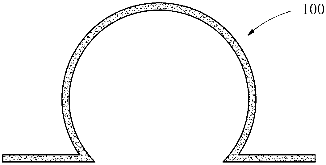
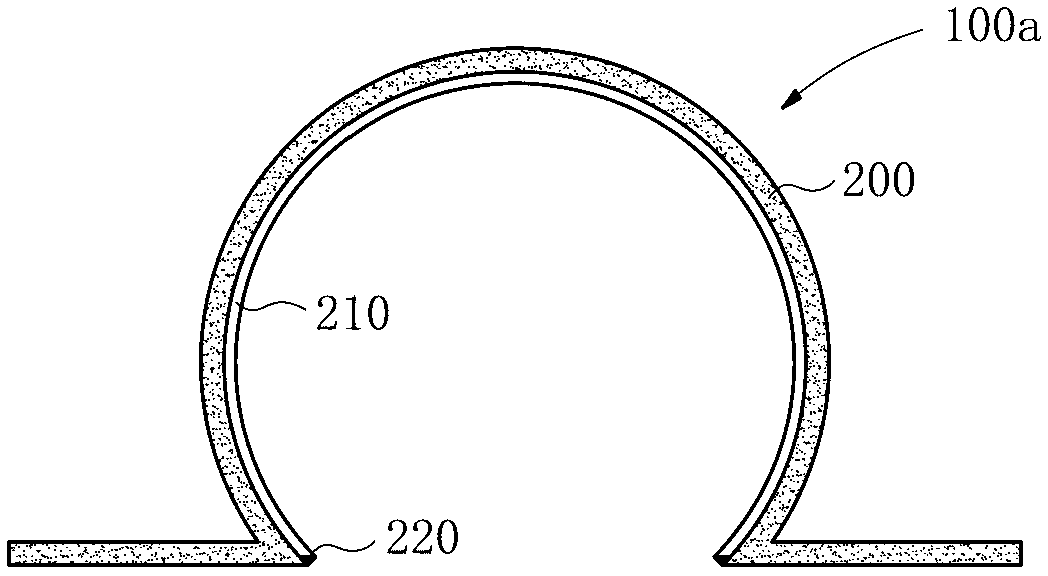
[0025] Here, the shape of the draft tube of the present invention may be an ohmic tube shape or a triangular tube shape, but is not limited thereto. For purposes of illustration, the invention will be described in connection with an ohmic tube shaped draft tube.

[0026] Furthermore, the vacuum infusion process according to the present invention is used to manufacture fan blades, but is not limited thereto. The present invention describes the process steps for manufacturing fan blades by using the vacuum infusion process of the present invention by way of illustration.

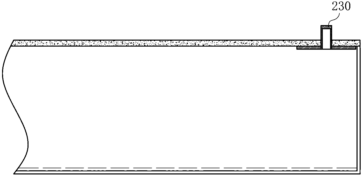
[0027] figure 1 is a sectional view showing a conventional draft tube, figure 2 and Figure 4 are cross-sectional views respectively showing the duct according to an exemplary embodiment of the present invention when it is no...


PUM


Abstract

The invention provides a vacuum infusion process and a drainage tube used for the vacuum infusion process. The process comprises the following steps of: paving glass fiber textile, release cloth, a perforated isolation membrane and a drainage mesh; paving the drainage tube, wherein the drainage tube comprises a drainage tube main body, a film lining or film bag and an injection port; paving a resin glue inlet tube, a glue inlet three-way tube and a vacuum tube; paving a vacuum bag so as to seal at a proper position of the component; opening a valve of the resin glue inlet tube so as to perform vacuum infusion; when the infusion process is about to be completed, connecting the injection port of the drainage tube main body by utilizing a connecting tube so as to inject a packing medium to enable the film lining or the film bag to be expanded, thus squeezing out resin inside the drainage tube main body; and infusing the remaining part of a product by utilizing the resin squeezed out, and then curing. The vacuum infusion process can solve the problems of material waste and the like caused by resin residual inside the drainage tube, and is beneficial to cleaning and recovery utilization of the drainage tube.

Description

technical field [0001] The invention relates to the technical field of vacuum infusion molding of composite materials, in particular to a vacuum infusion process for forming fan blades without residual resin and a guide pipe used in the process. Background technique [0002] Fan blades are usually thin-shell structures made of composite materials, which are basically composed of glass fiber fabrics, carbon fiber fabrics, or interlayers containing foam, etc. The molding of fan blades usually involves a vacuum infusion process. In the vacuum infusion process, a guide tube is often used to guide the resin to the guide net so that the resin can be evenly poured. Currently, there is usually a large amount of resin remaining in the nozzle after the vacuum infusion process is completed, for example, for the blade shell and its components (e.g. main spar preform, web Plate prefabricated parts, root prefabricated parts, etc.) usually have a length of several hundred meters. For the ...

Claims


Application Information

Patent Timeline
Patent Type & Authority Applications(China)
IPC IPC(8): B29C70/44B29C70/54
Inventor 李小明
Owner XINJIANG GOLDWIND SCI & TECH
Why Eureka
Try Eureka