Hydraulic brake controller

A hydraulic brake and controller technology, applied in bicycle brakes, hydraulic brake transmissions, bicycle accessories, etc., can solve problems such as affecting the braking sensitivity, affecting the time when the piston passes through the oil return hole, and the force of the piston dispersed, so as to achieve reliable lifting. The effect of perfect degree, structure and function

Inactive Publication Date: 2013-08-21
HENG TONG MACHINERY
View PDF6 Cites 4 Cited by
  • Summary
  • Abstract
  • Description
  • Claims
  • Application Information

AI Technical Summary

Problems solved by technology

[0005] However, when the rider presses the brake handle to drive the piston forward, before the piston passes through the oil return hole, part of the force of the brake handle is distributed to push the excess hydraulic oil back to the oil pot. After passing through the oil return hole

Method used


Image

  • Hydraulic brake controller
  • Hydraulic brake controller
  • Hydraulic brake controller

Examples


Embodiment Construction

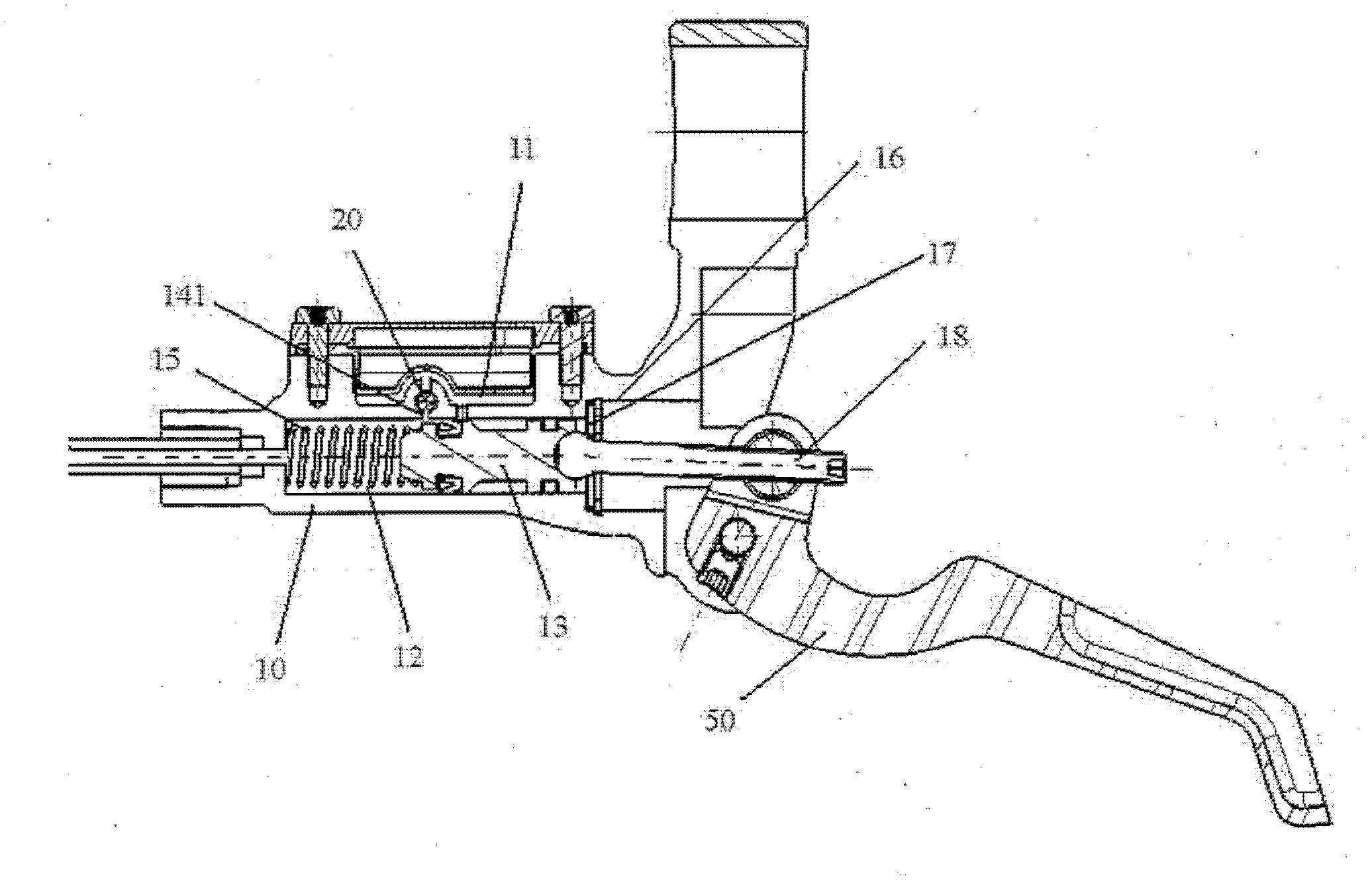
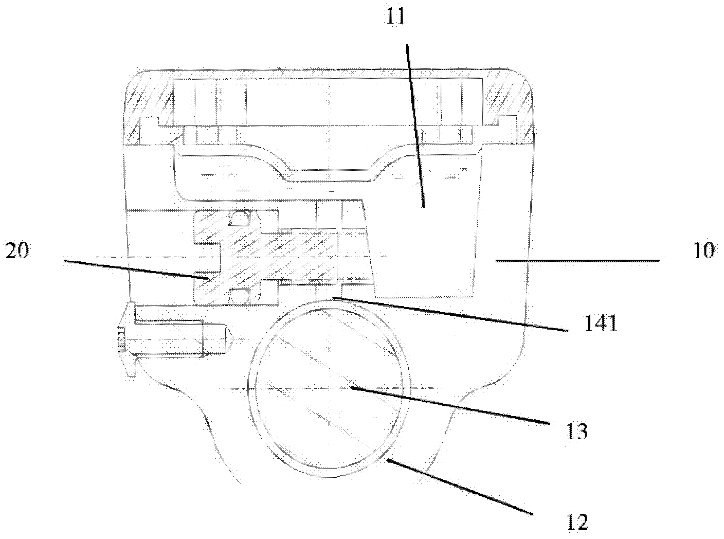
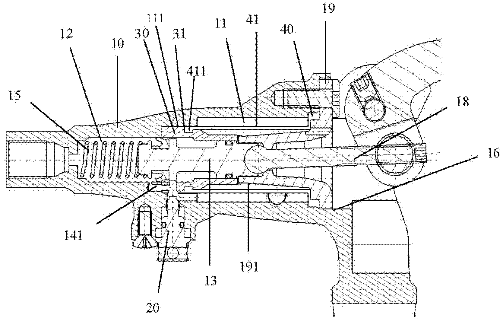
[0054] Such as figure 1 A sectional view of the axial structure of the hydraulic brake controller according to the first embodiment of the present invention, figure 2 As shown in the radial structural sectional view of the hydraulic brake controller of the first embodiment of the present invention, the hydraulic brake controller of the present invention is provided with an oil storage space 11 on a controller body 10 for storing hydraulic oil, and a main oil cylinder 12 for supplying hydraulic oil. Through the hydraulic pipeline (not shown in the figure), it is connected with the auxiliary oil cylinder of at least one brake caliper (not shown in the figure). The main oil cylinder 11 is further provided with a piston 13 that can be driven by the brake handle 50 to move back and forth relative to the inside of the main oil cylinder 12 .

[0055]It is characterized in that: the controller body 10 is provided with a first oil return hole 141 connected to the oil storage space 11...


PUM


Abstract

The invention mainly provides a hydraulic brake controller. The brake sensitivity can be conveniently adjusted by the aid of the hydraulic brake controller. The hydraulic brake controller is characterized in that a main cylinder is provided with a first oil return hole corresponding to a reciprocating stroke of a piston, the first oil return hole is connected to oil storage space, and an adjusting screw which extends into the first oil return hole is arranged on a main controller body in a screwed manner. The hydraulic brake controller has the advantages that the speed of hydraulic oil flowing back to the oil storage space can be controlled by means of simply changing the extension degree of the adjusting screw which extends into the oil return hole, accordingly, the duration when brake force of the piston completely acts on a brake pad via the oil return hole can be prolonged or shortened, and the purpose of conveniently adjusting the brake sensitivity is achieved.

Description

technical field [0001] The invention relates to a hydraulic brake controller, in particular to a hydraulic brake controller which is convenient for adjusting brake sensitivity. Background technique [0002] Press, the hydraulic brake device used by locomotives or bicycles should be regarded as one of the most commonly used hydraulic devices. It is mainly equipped with a brake controller driven by the brake handle at the handshake, and is connected to the Relative to the brake calipers located at the wheels; when the rider presses the brake handle, the handle drives a piston in the master cylinder relative to the brake controller body to move forward, pushing the hydraulic oil in the master cylinder into the brake calipers The auxiliary oil cylinder makes the brake pad at the auxiliary oil cylinder advance towards the direction of the brake disc, and uses the brake pad to contact the brake disc on the wheel hub, thereby generating a detent action on the wheel. And, when the ...

Claims


Application Information

Patent Timeline
IPC IPC(8): B62L3/02B60T11/10
Inventor 王淳钦
Owner HENG TONG MACHINERY
Why Eureka
Try Eureka