Combined ice-breaking equipment and method of notching and hull pressure

A kind of ice-breaking equipment and groove cutting technology, applied in the direction of ice-breaking ships, etc., can solve the problems of unfavorable ship advance, limited lateral width of ice-breaking area, limited ice-breaking ability of ice-breaking ships, etc., and achieve the effect of improving ice-breaking ability and continuous ice-breaking

Active Publication Date: 2016-08-31
NORTH CHINA UNIV OF WATER RESOURCES & ELECTRIC POWER
View PDF8 Cites 0 Cited by
  • Summary
  • Abstract
  • Description
  • Claims
  • Application Information

AI Technical Summary

Problems solved by technology

However, during the icebreaking process of ordinary icebreakers, the stress on the ice sheet decreases from the center of the contact point between the ship and the ice sheet to the surroundings. The lateral width of the icebreaking area is limited, which is not conducive to the advancement of the ship. The icebreaking ability of the icebreaker is limited.

Method used


Image

  • Combined ice-breaking equipment and method of notching and hull pressure

Examples


Embodiment 1

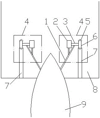
[0014] Depend on figure 1 The combined ice-breaking equipment for slotting and hull pressure shown is a combined ice-breaking equipment for slotting and hull pressure. 9 are set symmetrically on both sides.

[0015] The ice breaking device 4 includes an outrigger 1, a milling cutter provided on the outrigger 1, and a power unit connected with the milling cutter on the outrigger 1, and the rear end of the outrigger 1 is connected to the hull 9 of the icebreaker 1. The front end extends to the front of the hull 9 outside, and the milling cutter and the power unit driving the milling cutter to rotate are all arranged on the front end of the outrigger 1 . The milling cutter is arranged horizontally, and the axial direction of the milling cutter is the width direction of the icebreaker, that is, the central axis of the milling cutter extends along the width direction of the icebreaker hull 9 . The milling cutter comprises a cutter bar 3 and a cutter head arranged on the cutter ba...

Embodiment 2

[0018] Depend on figure 1 The combined icebreaking method of grooving and hull pressure shown is realized on the basis of Example 1. First, the combined icebreaking equipment of grooving and hull pressure described in Example 1 is prepared, and the icebreaker travels on the frozen river surface When the power unit drives the milling cutter to rotate, before the icebreaker travels to the ice surface 8, the two milling cutters of the two icebreaking devices 4 mill out two cutting grooves 7 on the ice surface 8 on both sides in front of the icebreaker hull 9, and the icebreaker hull 9 travels During the process, it is pressed on the ice surface 8 between the two cutting grooves 7, and the cutting groove 7 and the icebreaker apply pressure to jointly break the ice.

[0019] The combined ice-breaking method of grooving and pressure application cuts the ice sheet by grooving, resulting in changes in the stress on the cross-section at the grooving place. The stress in the middle of ...


PUM


Abstract

The invention discloses a groove cutting and hull pressing combination ice breaker and an ice breaking method. The groove cutting and hull pressing combination ice breaker comprises an ice breaking ship, wherein two sides of a hull of the ice breaking ship are respectively provided with an ice breaking device. Each ice breaking device comprises an outrigger, a milling cutter arranged on the outrigger and a power device which is arranged on the outrigger and is in driving connection with the milling cutter. The axial direction of each milling cutter is the width direction of the ice breaking ship. The hull of the ice breaking ship is located between the two milling cutters of the two ice breaking devices. The two milling cutters of the two outriggers are both located on the front side of the hull of the ice breaking ship. The groove cutting and hull pressing combination ice breaking method is the ice breaking method implemented on the basis of the groove cutting and hull pressing combination ice breaker. The groove cutting and hull pressing combination ice breaker and the ice breaking method are beneficial to advancing of the ice breaking ship and can improve the ice breaking capacity of the ice breaking ship.

Description

technical field [0001] The invention relates to a combined ice-breaking device and method of grooving and hull pressure. Background technique [0002] Ice disasters occur frequently on the Yellow River, especially in the Inner Mongolia section and the Shandong section of Henan Province. In order to prevent ice flood disasters, the most commonly used method on the Yellow River is to break the ice with explosions. Since it requires the use of national defense forces, the cost is too high, and it is easy to form a secondary ice dam, which poses a major safety hazard. Explosive ice-breaking is not the most ideal measure for ice-breaking and ice-breaking. In the 1950s, two icebreakers "Keling" were built in the lower reaches of the Yellow River, with a draft of 1.4 m and a displacement of 1.475×10 5 kg, at a speed of 3 km per hour, it can break ice with a thickness of 0.33 m, and use ballast water tanks to break ice up to a maximum of 0.45 m. The "Keling" Yellow River icebrea...

Claims


Application Information

Patent Timeline
Patent Type & Authority Patents(China)
IPC IPC(8): B63B35/12
Inventor 郝用兴郭术义许兰贵程海涛马得朝杨松伟
Owner NORTH CHINA UNIV OF WATER RESOURCES & ELECTRIC POWER
Why Eureka
Try Eureka