
A combined LED lamp driving module

A technology of LED lamps and drive modules, applied in lighting and heating equipment, components of lighting devices, light sources, etc., can solve the problems of increasing the heat dissipation load of lamps, being unable to deal with them, and accelerating aging, so as to achieve good practicability and flexibility performance, reduce maintenance costs, and improve stability

Active Publication Date: 2019-01-25
沈阳北方防爆股份有限公司
View PDF6 Cites 0 Cited by
  • Summary
  • Abstract
  • Description
  • Claims
  • Application Information

AI Technical Summary

Problems solved by technology

Most of the LED lamps in the prior art arrange the heat dissipation module and the driving power module together in the same housing (lamp body), and even install the driving power module inside the radiator, so that after a long time of lighting, the LED The released heat energy and the heat energy of the electronic components of the driving power supply will accumulate together and have a great impact on the driving power supply and the LED light source itself, resulting in unstable circuit operation, accelerated aging and reduced service life, and also increases the heat dissipation load of the lamp. Make the structure of the luminaire constrained
In addition, the current LED lamps still have the problem that the life of electronic components is far less than the life of LED light sources. The life of capacitors is often only one-tenth of the life of LED power supplies. Therefore, compared with the life of LED light sources, the maintenance rate of electronic components is very high. of
Moreover, the LED lamps of the prior art are rarely equipped with emergency functions, and even if there are, the emergency time is within a few minutes, which is far from being able to deal with emergency situations such as sudden power failures and lamp failure maintenance situations.

Method used


Image

  • A combined LED lamp driving module
  • A combined LED lamp driving module
  • A combined LED lamp driving module

Examples


Embodiment Construction

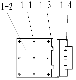
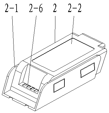
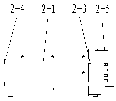
[0032] Please compare figure 1 , figure 2 , image 3 , Figure 4 , Figure 5 , the present invention is made up of control box 1 and power supply box 2.

[0033] in:

[0034] The control box 1 is composed of the control box base 1-2, the control box upper cover 1-1 and the controller module and its kit. The size of the control box base 1-2 corresponds to the opening of the control box upper cover 1-1, and one side is flat , the other side has studs for installing the controller module, the bottom plate is reserved with mounting holes corresponding to the mounting studs on the upper cover of the control box 1-1, and two protruding control The box docking positioning buckle 1-3; the control box upper cover 1-1 is a cavity with an opening at the bottom, and the opening is the installation position of the control box base 1-2, that is, the control box base 1 is reserved on the inner side of the opening -2 studs; the front end of the control box upper cover 1-1 has a protrud...


PUM


Abstract

The invention discloses a combined LED lamp driving module which comprises a controlling case and power source cases. A controller module is both a driving power source module of a lamp and a controlling module having functions of detecting and automatically switching to a stand-by power source when the lamp is out of power or order. The controlling case and the power source cases are connected in a sleeved mode. The power source cases can be connected by multiple connectors in a sleeved mode. The controlling case is in butt joint with the lamp in an inserted mode by means of cable extending, so that instant power supply and real-time monitoring for the lamp and emergent power supply and real-time charging when necessary are realized. The combined LED lamp driving module has the advantages of convenience in mounting and dismounting, combination flexibility, convenience in maintenance, higher stability of driving power source, long service life of the whole lamp, and the like.

Description

technical field [0001] The invention belongs to the technical field of LED lighting and relates to a combined LED lamp driving module. Background technique [0002] LED has been widely used as a new green lighting source. Its lamps are mainly composed of four parts: LED light source module, heat dissipation module, driving power module, lens or reflector. Most of the LED lamps in the prior art arrange the cooling module and the driving power module together in the same housing (lamp body), and even install the driving power module inside the radiator. The released heat energy and the heat energy of the electronic components of the driving power supply will accumulate together and have a great impact on the driving power supply and the LED light source itself, resulting in unstable circuit operation, accelerated aging, and reduced service life. At the same time, it also increases the heat dissipation load of the lamp. Make the structure of the luminaire constrained. In addi...

Claims


Application Information

Patent Timeline
Patent Type & Authority Patents(China)
IPC IPC(8): F21V23/06F21V23/00F21V17/12F21Y115/10
Inventor 谢凌龙赵勇杨丽
Owner 沈阳北方防爆股份有限公司
Learn More