Piston mechanism with breakdown protection device
A piston mechanism and protection device technology, applied in the field of pressure vacuum gauges, can solve problems such as delays in work, cycle recovery, and influence on normal operations, and achieve the effect of ensuring normal operation
- Summary
- Abstract
- Description
- Claims
- Application Information
AI Technical Summary
Problems solved by technology
Method used
Image

Examples
Embodiment Construction
[0012] In order to make the technical means, creative features, goals and effects achieved by the present invention easy to understand, the present invention will be further described below in conjunction with specific illustrations.
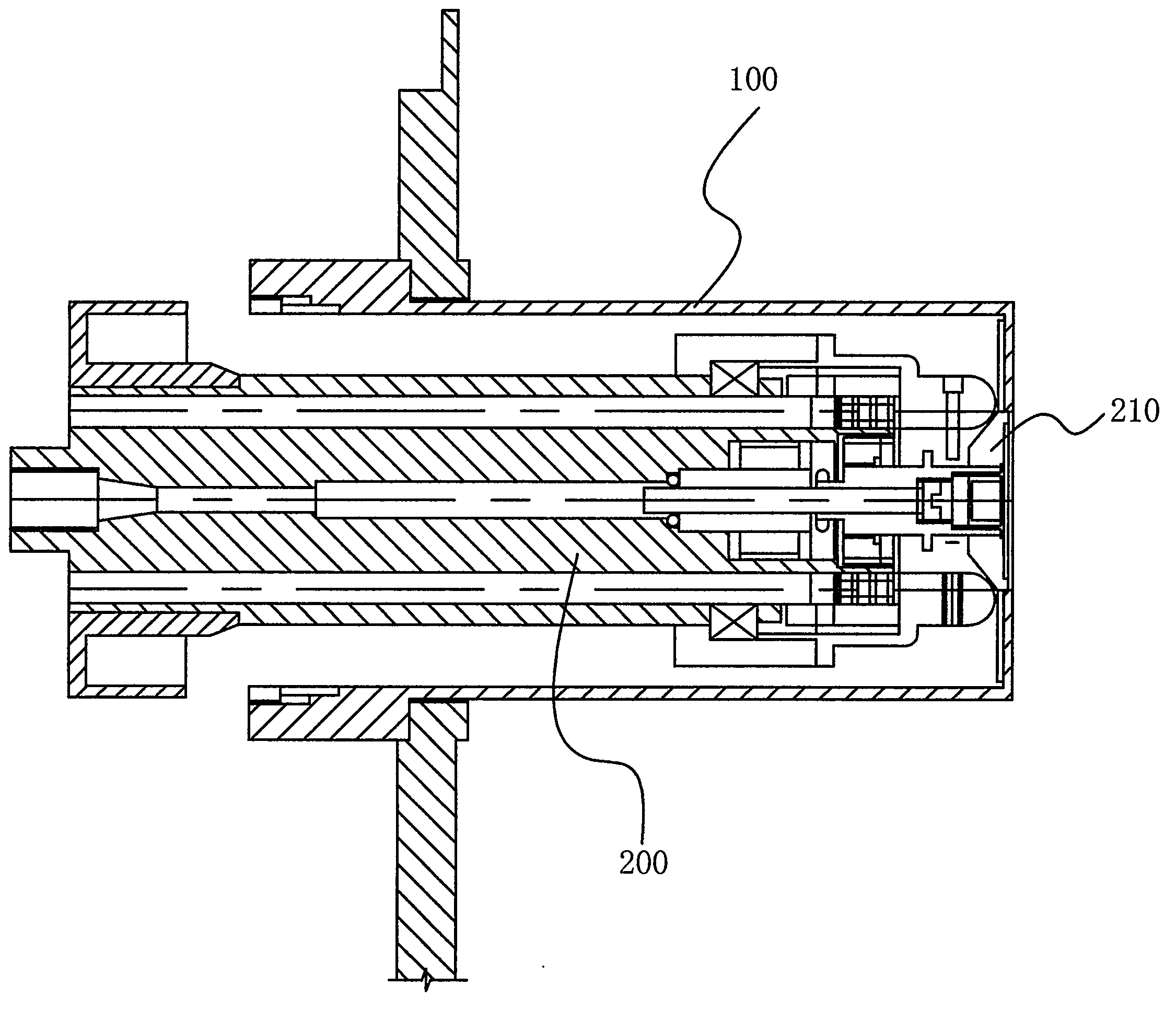
[0013] see figure 1 , figure 1 It is a structural schematic diagram of a piston mechanism in the prior art, including a piston cylinder 100, a piston rod 200 and a detachable piston rod tray 210 arranged at the top of the piston rod 200, and one end of the piston rod 200 provided with the piston rod tray 210 extends into the piston cylinder 100 middle. During work, when it is necessary to install additional weights or reduce the number of weights, if there is a large deviation in verticality due to improper operation, the piston rod 200 cannot bear the large deviation angle, and the piston rod will be broken. Why there is a large deviation angle, because the height of the hanging basket is 157MM, the gap between the inner hole and the diameter...
PUM
 Abstract
Description
Claims
Application Information