
Arrangement for component test stand

A test bench and equipment technology, applied in the equipment field of component test benches, can solve the problems of regular replacement, lack of protection, damage, etc., and achieve the effect of reliable impact energy

Active Publication Date: 2013-08-21
SCHAEFFLER TECH AG & CO KG
View PDF11 Cites 0 Cited by
  • Summary
  • Abstract
  • Description
  • Claims
  • Application Information

AI Technical Summary

Problems solved by technology

The disadvantage here is that the forces acting in this way can cause damage to the corresponding bearing or to the rotary drive or a clutch connected thereto or a transmission connected thereto, which can lead to repair times and downtime time, because the bearing bracket must be replaced periodically after an imbalance due to lack of protection
In addition to this bearing damage, the shaft itself can also bend, which can lead to replacement of the shaft due to excessively high plastic deformation
[0004] The disadvantages of the solutions known from the prior art are therefore that the bearings have to be replaced after some tests or that the test specimens can only be tested with small unbalanced forces

Method used


Image

  • Arrangement for component test stand
  • Arrangement for component test stand
  • Arrangement for component test stand

Examples


Embodiment Construction

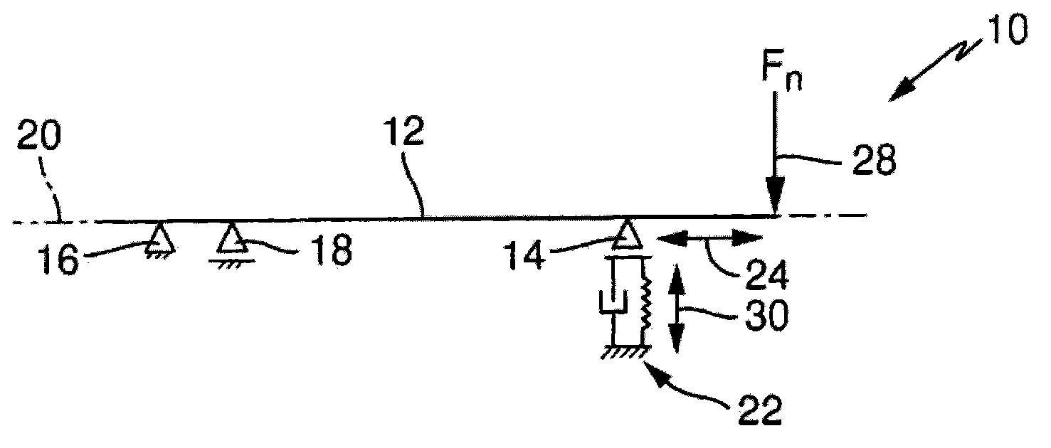
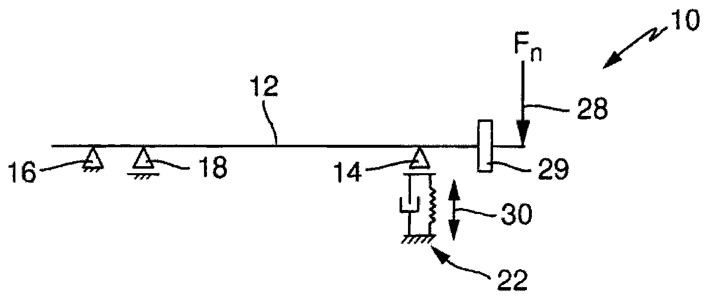
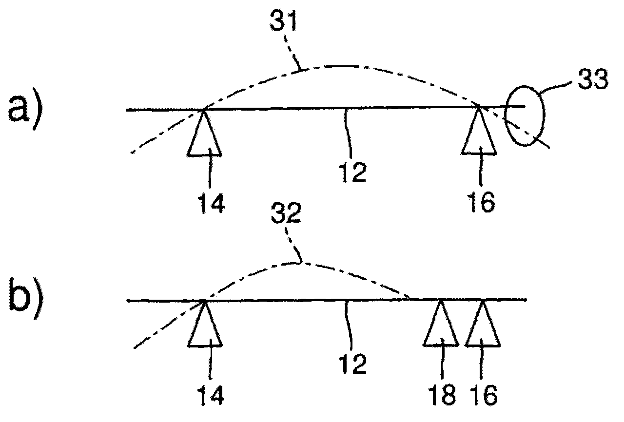
[0033] figure 1 The device 10 shown in , can be used in particular in component test stands for testing test specimens. The device 10 includes a shaft 12 for transmitting a rotational force from a not shown rotary drive to a likewise not shown component to be inspected. In this case, the shaft 12 is rotatably mounted on the component side in at least one bearing 14 and also rotatably mounted on the drive side in at least one bearing 16 . Preferably, the shaft 12 can be mounted rotatably on the drive side in two bearings 16 , 18 arranged one behind the other along the axis 20 of the shaft. The bearing 16 of the two bearings 16 , 18 facing the drive side can be designed as a fixed bearing, whereas the bearing 18 facing the component side can be designed as a floating bearing. Furthermore, the component-side bearing 14 can also be designed as a non-locating bearing.

[0034] also figure 1 It is shown that the component-side bearing 14 is connected to a damping system 22 in or...


PUM


Abstract

The arrangement (10) comprises a shaft (12) for transferring a rotational force from a rotational drive to a component to be tested, where the shaft is rotatably supported in a component side bearing (14) and a drive side bearing (16). The component side bearing is connected with a damping system (22). The arrangement for component stand can damp unbalanced force, and thus components of the component test stand can be protected.

Description

technical field [0001] The invention relates to an apparatus for a component testing stand according to the features of claim 1, which comprises a shaft for transmitting a rotational force from a rotary drive to the component to be inspected. Background technique [0002] A device for a component test bench comprising a shaft for transmitting a rotational force from a rotary drive to the component to be tested is known, for example, from DE 1 125 206 . This document discloses a component test stand in which the test specimen is subjected to centrifugal forces as required up to the fracture limit in an evacuated receptacle lined with a protective wall. A small air turbine, which is arranged in a hood, can be used here as the drive unit. In this case, the cover of the receiver is fastened rigidly to a crossbeam in which the air turbine and all supply and discharge lines are also accommodated. A thin drive shaft protrudes from the housing of the air turbine through the shroud...

Claims


Application Information

Patent Timeline
IPC IPC(8): G01M13/00
CPCG01M13/00G01M13/04G01M13/045
Inventor J·苏克S·贝伦茨C·布莱斯
Owner SCHAEFFLER TECH AG & CO KG
Learn More