Unlock instant, AI-driven research and patent intelligence for your innovation.

Linear constant-current modulation circuit

A modulation circuit, linear constant current technology, applied in the direction of regulating electrical variables, control/regulating systems, instruments, etc., can solve problems such as large power tubes, improve stability and reliability, and eliminate adverse effects.

Active Publication Date: 2014-12-24
MAXIC TECHNOLOGY CORPORATION
View PDF6 Cites 0 Cited by
  • Summary
  • Abstract
  • Description
  • Claims
  • Application Information

AI Technical Summary

Problems solved by technology

Especially when the input voltage Vin is far greater than the load voltage drop VL, the power borne by the power tube is very large, and the heating situation will be serious

Method used


Image

  • Linear constant-current modulation circuit
  • Linear constant-current modulation circuit
  • Linear constant-current modulation circuit

Examples


Embodiment Construction

[0016] In order to express the technical solutions and advantages of the embodiments of the present invention more clearly, the technical solutions of the present invention will be further described in detail below with reference to the drawings and embodiments.

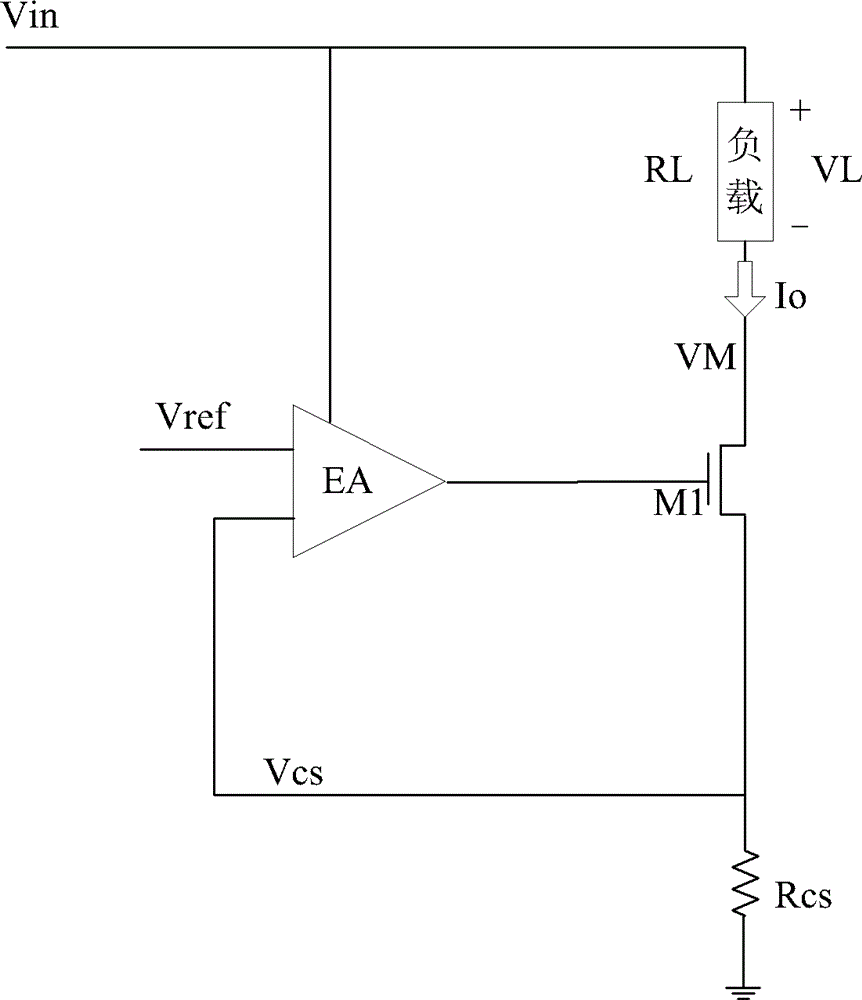
[0017] image 3 The linear constant current modulation circuit provided for the embodiment of the present invention; as image 3 As shown, the constant current control circuit includes a heat dissipation circuit and an existing constant current control circuit; wherein, the heat dissipation circuit includes: a voltage detection circuit, a switch tube M2 and several external resistors Rext; the existing constant current control circuit includes an input voltage Vin, Load device, power tube M1, error amplifier EA, reference voltage Vref, feedback voltage Vcs and resistor Rcs.

[0018] It should be noted that the load device in the embodiment of the present invention is a resistor, a light-emitting diode (LED) and othe...


PUM


Abstract

The invention relates to a linear constant-current modulation circuit which comprises a voltage detection circuit, a power tube (M1), a switch tube (M2) and a plurality of resistors (Rext). The power tube (M1) is serially connected with the switch tube (M2), the switch tube (M2) is connected with the resistors (Rext) in parallel, the voltage detection circuit detects voltage difference (VM1) of two ends of the power tube (M1), and the switch tube (M2) is in a cut-off state under the control of the voltage detection circuit when the voltage difference (VM1) exceeds a preset threshold voltage (VMT). The linear constant-current modulation circuit has the advantages that adverse effect on a constant-current circuit when working power of an existing power tube is excessively high is eliminated, and the operational stability and the operational reliability of the linear constant-current modulation circuit are improved.

Description

technical field [0001] The invention relates to the field of integrated circuits, in particular to a linear constant current modulation circuit. Background technique [0002] At present, the linear constant current modulation circuit is a unit circuit widely used in analog integrated circuits, and has a wide range of applications in practice. In the linear constant current modulation circuit, see figure 1 , The error amplifier (EA) modulates the power tube (M1) by comparing and amplifying the feedback voltage (Vcs) with the internal reference level (Vref), thereby precisely controlling the constant current (Io). The calculation formula is: [0003] Io=Vref / Rcs (1) [0004] VL=Io*RL (2) [0005] VM=Vin-VL (3) [0006] PM1=VM*Io=(Vin-VL)*Io (4) [0007] When the impedance RL of the load does not change much, the voltage drop VL on it will basically remain unchanged when the constant current Io flows, then when the input voltage Vin changes, the voltage drop VM dropped on...

Claims


Application Information

Patent Timeline
Patent Type & Authority Patents(China)
IPC IPC(8): G05F1/46
Inventor 刘柳胜
Owner MAXIC TECHNOLOGY CORPORATION
Features
  • R&D
  • Intellectual Property
  • Life Sciences
  • Materials
  • Tech Scout
  • Unparalleled Data Quality
  • Higher Quality Content
  • 60% Fewer Hallucinations
Learn More