
Light-emitting diode (LED) lamp board assembly

A technology of LED lamp panels and LED lamps, which is applied to components of lighting devices, semiconductor devices of light-emitting elements, lighting devices, etc., can solve problems such as large splicing gaps and difficulty in ensuring straightness, and achieve small splicing gaps and reduced Stitching gap, processing accuracy is easy to guarantee the effect

Inactive Publication Date: 2013-08-21
LEYARD
View PDF12 Cites 3 Cited by
  • Summary
  • Abstract
  • Description
  • Claims
  • Application Information

AI Technical Summary

Problems solved by technology

[0003] The splicing edges of the LED screens in the prior art are all linear. Since the length of each splicing edge is relatively long, it is difficult to guarantee the straightness during processing.
In this way, when multiple screen modules are spliced ​​together, the splicing gap will be large

Method used


Image

  • Light-emitting diode (LED) lamp board assembly
  • Light-emitting diode (LED) lamp board assembly
  • Light-emitting diode (LED) lamp board assembly

Examples


Embodiment Construction

[0024] It should be noted that, in the case of no conflict, the embodiments in the present application and the features in the embodiments can be combined with each other. The present invention will be described in detail below with reference to the accompanying drawings and examples.

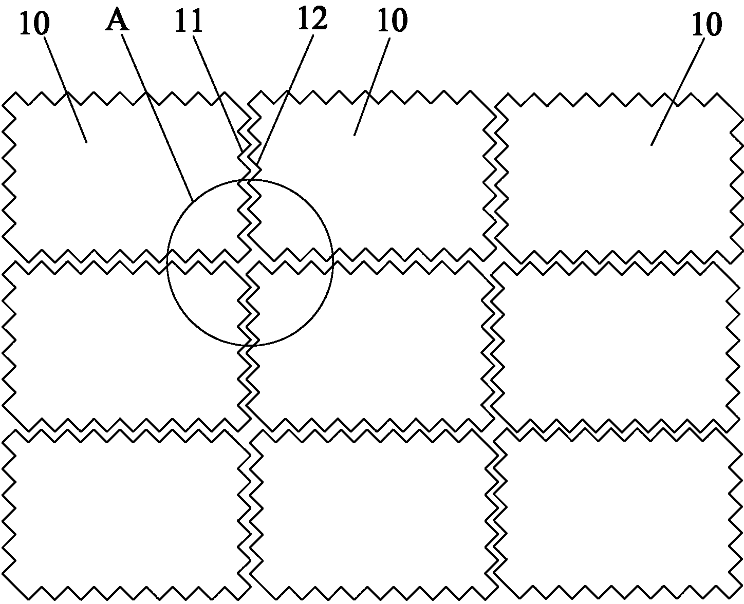
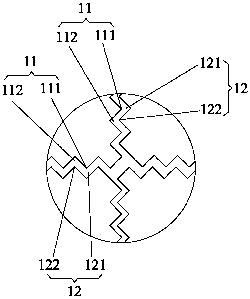
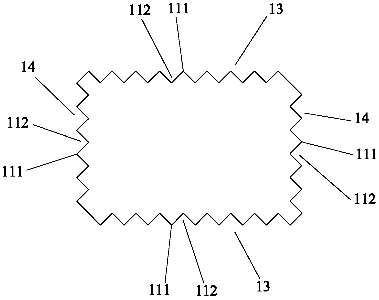
[0025] like Figure 1 to Figure 2 As shown, the LED lamp panel assembly of Embodiment 1 includes a plurality of LED lamp panels 10 spliced ​​with each other, and a splicing part is formed between adjacent LED lamp panels 10, and the splicing part includes the first splicing edge 11 and the first splicing edge 11. The second splicing edge 12 that is structurally adapted. The first splicing edge 11 is provided with a plurality of first connecting convex parts 111 and a plurality of first connecting concave parts 112 at intervals. The second splicing edge 12 is provided with a plurality of first The plurality of second connection recesses 121 that are shape-fitted to the connection protrusions 11...


PUM


Abstract

The invention provides a light-emitting diode (LED) lamp board assembly which comprises a plurality of LED lamp boards (10) which are spliced mutually. Splicing portions are arranged between adjacent LED lamp boards (10). Each splicing portion comprises a first splicing edge (11) and a second splicing edge (12) adaptive to the first splicing edge (11) in terms of structure. A plurality of first connection protruded portions (111) and a plurality of first connection concave portions (121) are arranged on each first splicing edge (11) at intervals, a plurality of second connection concave portions (121) adaptive to the first connection protruded portions (111) in terms of shape and a plurality of second connection protruded portions (122) adaptive to the first connection concave portions (112) in terms of shape are arranged in each second splicing edge (12). The LED lamp board assembly can effectively reduce splicing gaps.

Description

technical field [0001] The invention relates to the technical field of LED display, in particular to an LED lamp panel assembly. Background technique [0002] Existing LED screens are generally rectangular screen modules, and some spherical screens generally use triangular or regular hexagonal screen modules. The splicing between the screen modules generally fixes the screen modules directly on the brackets by screws. [0003] The splicing edges of the LED screens in the prior art are all linear. Since the length of each splicing edge is relatively long, it is difficult to guarantee the straightness during processing. In this way, when multiple screen modules are spliced ​​together, the splicing gap will be large. Contents of the invention [0004] The present invention aims to provide an LED lamp panel assembly capable of effectively reducing the splicing gap. [0005] In order to achieve the above object, the present invention provides an LED lamp panel assembly, whic...

Claims


Application Information

Patent Timeline
Patent Type & Authority Applications(China)
IPC IPC(8): G09F9/33F21V21/00F21Y101/02F21Y105/14F21Y115/10
Inventor 刘志勇王杰余杰
Owner LEYARD
Learn More