Automatic change-over switch device

A technology of automatic transfer switches and moving contacts, which is applied in the direction of electric switches, electrical components, circuits, etc., can solve the problems of many parts, prone to failure, cumbersome processing, manufacturing and maintenance, etc., and achieve stable and reliable working performance and few fault sources , the effect of rational and simplified structure

Inactive Publication Date: 2013-08-21
SUZHOU JUNFENGCHEN ELECTRONICS TECH
View PDF6 Cites 0 Cited by
  • Summary
  • Abstract
  • Description
  • Claims
  • Application Information

AI Technical Summary

Problems solved by technology

[0003] The structure of the centrifugal switch used in the traditional motor is relatively complicated, and the processing, manufacturing and maintenance are relatively cumbersome, and due to the large number of parts, it is prone to failure, and its structure needs to be improved urgently.

Method used


Image

  • Automatic change-over switch device
  • Automatic change-over switch device
  • Automatic change-over switch device

Examples


Embodiment 1)

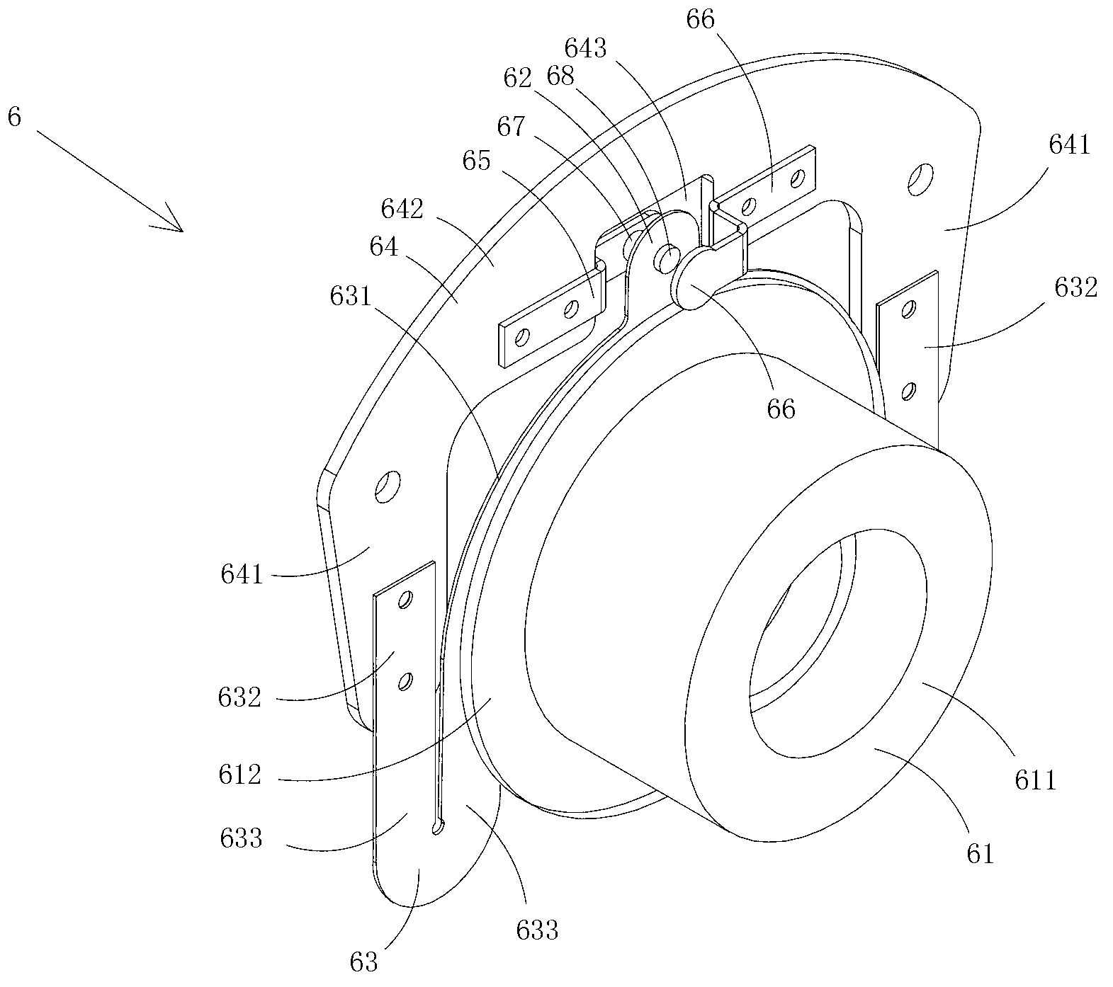
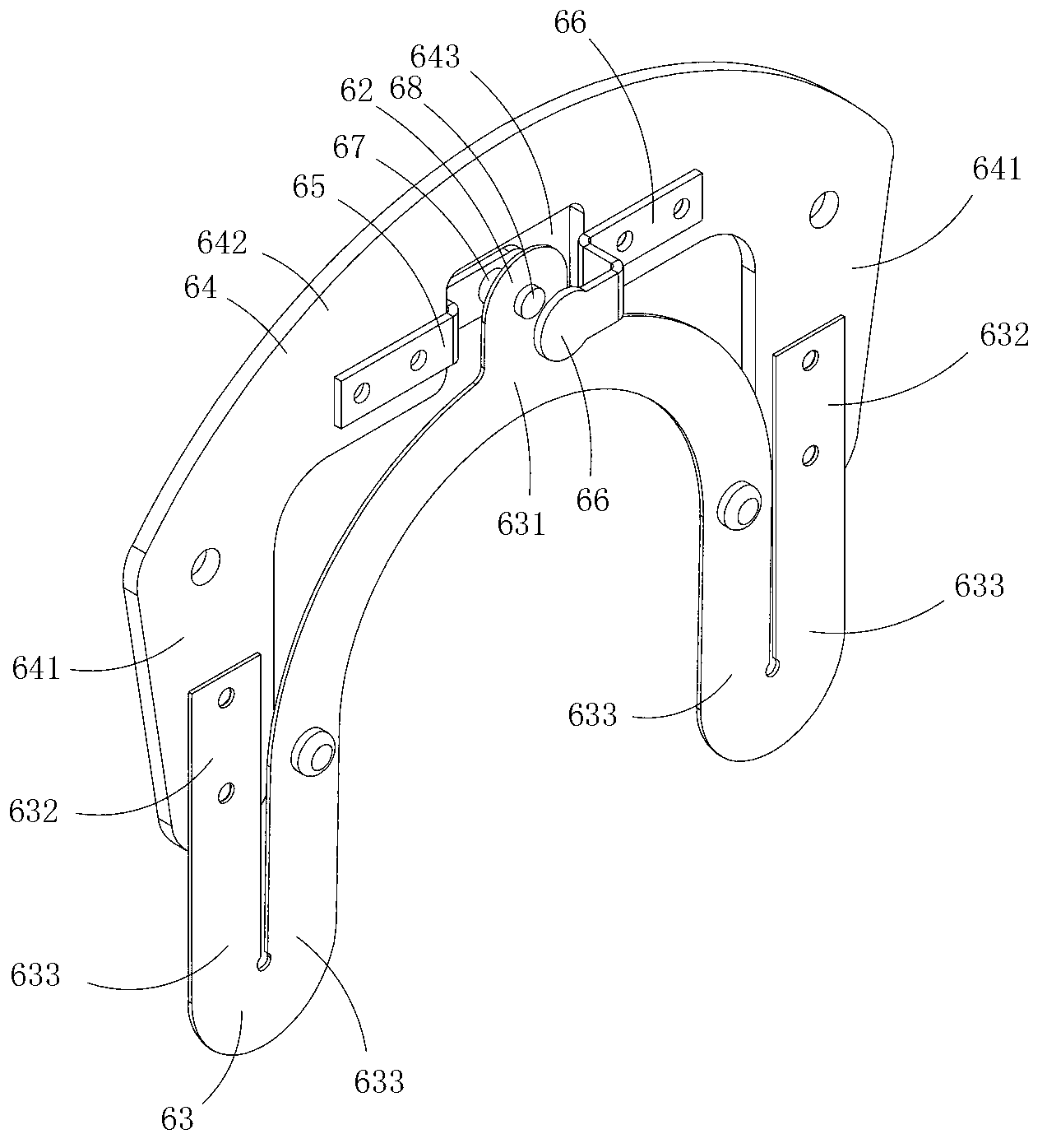
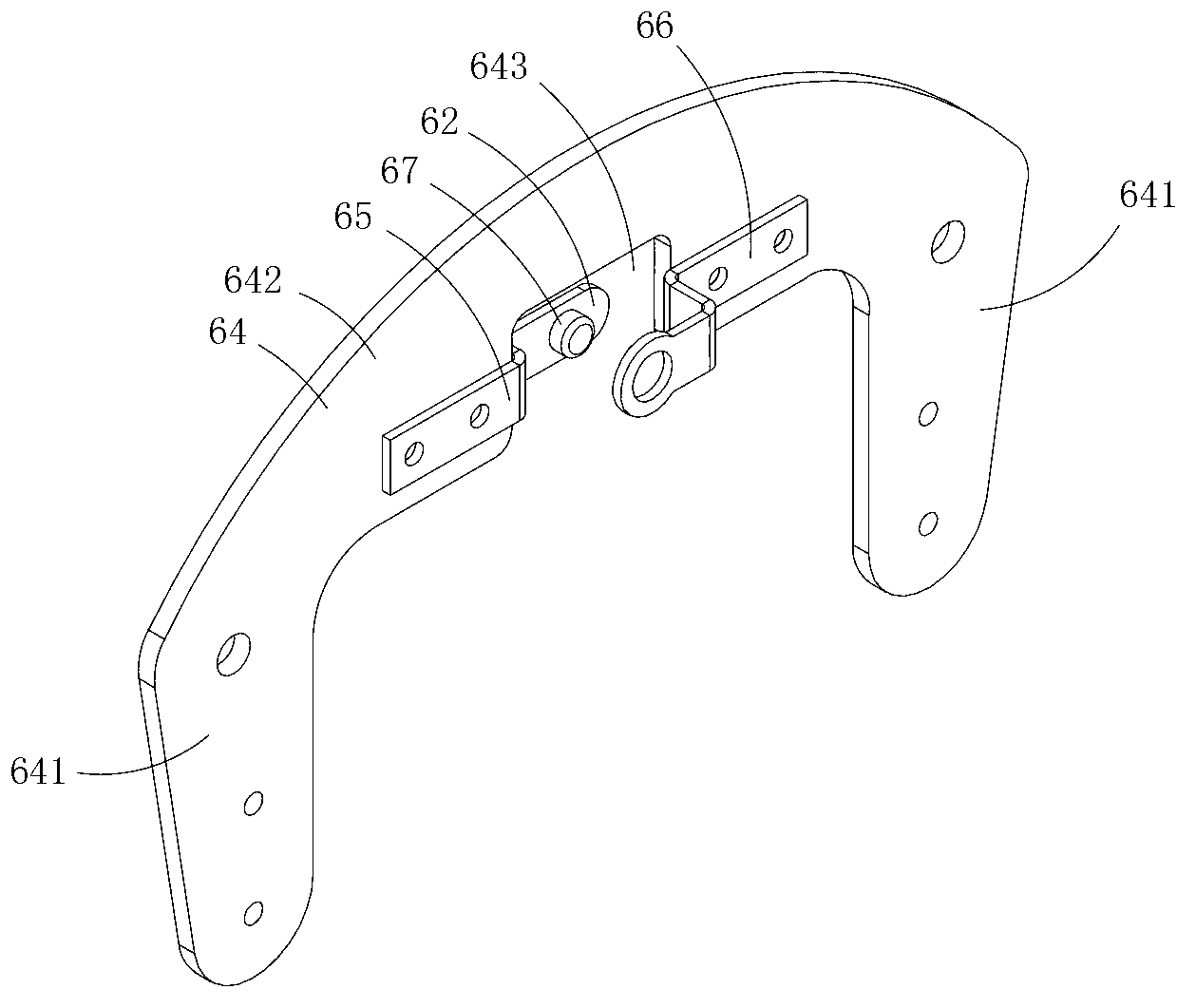
[0018] Figure 1 to Figure 4 A first embodiment of the invention is shown, in which figure 1 It is a schematic diagram of a three-dimensional structure of the present invention; figure 2 for figure 1 A schematic diagram of the three-dimensional structure of the switching device shown after removing the centrifugal slider; image 3 for figure 1 A schematic diagram of a three-dimensional structure of the insulating fixing plate in the switchgear shown; Figure 4 for figure 1 A schematic diagram of the three-dimensional structure of the elastic member in the switch device shown.

[0019] This embodiment is an automatic transfer switch device, see Figure 1 to Figure 4 , including a centrifugal slider 61, an elastic member 63 provided with a moving contact 62, and an insulating fixed plate 64 provided with a first static contact 65 and a second static contact 66; Move back and forth in the direction; the moving contact can move between the first static contact and the seco...


PUM


Abstract

The invention discloses an automatic change-over switch device which comprises a centrifugal slide block, an elastic part provided with a movable contact and an insulating fixed plate provided with a first static contact and a second static contact. The centrifugal slide block can move in a reciprocation mode in the central axial direction, the movable contact can move between the first static contact and the second static contact along with the centrifugal slide block until abutting against on the first static contact or the second static contact, the insulating fixed plate is basically in a U shaped and comprises two connection areas and a base area arranged between the two connection areas, and the first static contact and the second static contact are arranged in the base area. The elastic part comprises an arc electric connection plate area, installation plate areas fixedly arranged on the connection areas of the insulating fixed plate and U-shaped elastic plate areas for connecting the electric connection plate area and the installation plate areas, wherein the electric connection plate areas are fixedly arranged on the centrifugal slide block and can synchronously move along with the centrifugal slide block. The automatic change-cover switch device is simple and reasonable in structure, few in fault source and stable and reliable in work performance.

Description

technical field [0001] The invention belongs to the field of motor structure design, and in particular relates to an automatic transfer switch device. Background technique [0002] In order to solve the starting current problem of single-phase motors, it is necessary to set an automatic transfer switch on the shaft of the single-phase motor, and the circuit is connected in series in the starting circuit. When starting, the starting circuit starts to start through the conduction of the centrifugal switch. When the centrifugal switch reaches a certain speed, the centrifugal switch is disconnected to automatically cut off the starting circuit. After the starting is completed, the motor becomes in the running state. [0003] The structure of the centrifugal switch used in traditional motors is relatively complicated, and the processing, manufacturing and maintenance are relatively cumbersome, and due to the large number of parts, it is prone to failure, and its structure needs t...

Claims


Application Information

Patent Timeline
Patent Type & Authority Applications(China)
IPC IPC(8): H01H35/10
Inventor 刘仁山
Owner SUZHOU JUNFENGCHEN ELECTRONICS TECH
Why Eureka
Try Eureka