

Bladder intermittent drainage system
A bladder and drainage bag technology, which is applied to drainage devices, wound drainage devices, suction devices, etc., can solve the problems of inconvenient operation, increased nursing work, and failure to urinate in time, and achieves a simple structure and convenient operation. Effect
- Summary
- Abstract
- Description
- Claims
- Application Information
AI Technical Summary
Benefits of technology
Problems solved by technology
Method used
Image

Examples
Embodiment 1
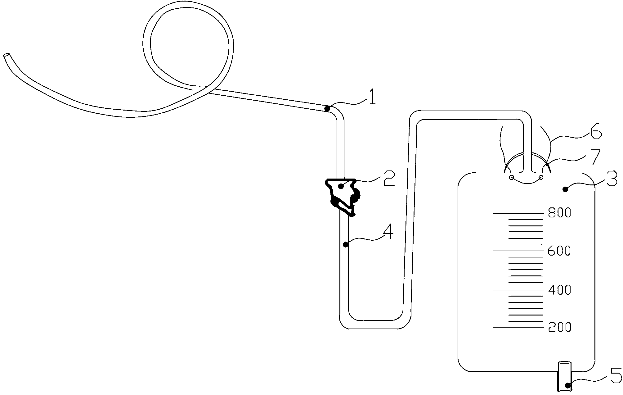
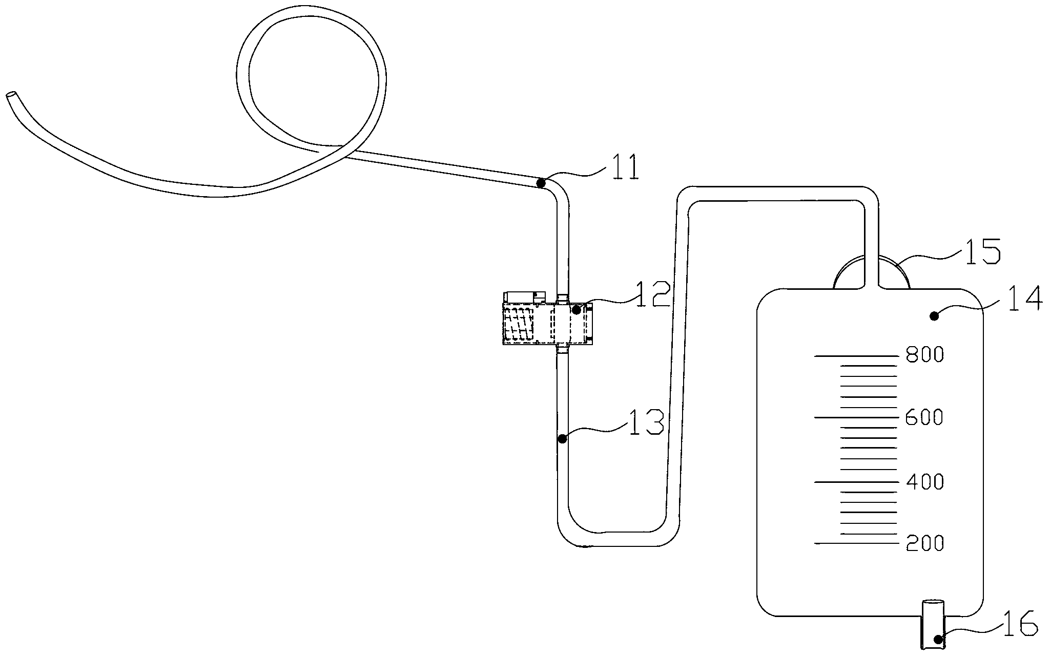
[0032] Such as image 3 A bladder intermittent drainage device shown, wherein the controllable conduction switch 12 is as Figure 4 to Figure 7As shown, it includes a casing 121, a conduction slider 122, a power supply 123 and a controller 124 installed on the casing 121, and a urinary tube interface end 1211 is provided on the upper surface of the casing 121. The urinary tube The interface end 1211 communicates with the inner cavity of the housing 121 , and a drainage bag interface end 1212 is provided on the lower surface of the housing 121 , and the drainage bag interface end 1212 is also communicated with the inner cavity of the housing 121 .
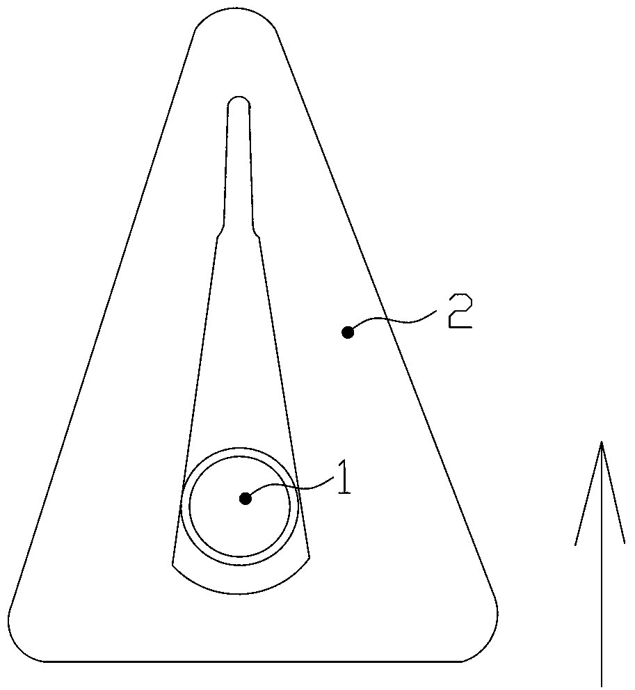
[0033] The conducting slider 122 is installed at the right end of the inner chamber of the housing 121 . The conduction slider 122 is divided into a conduction section 1221 located at the right end and a blocking section 1222 located at the left end. Taking the center line connecting the upper and lower end surfaces of the conducti...
Embodiment 2
[0038] Such as image 3 A bladder intermittent drainage device shown, wherein the controllable conduction switch 12 is as Figure 8 and Figure 9 As shown, its structure is basically the same as that of Embodiment 1, and will not be repeated here. The difference is that the right inner cavity surface of the housing 121 is a zigzag end surface; the conducting slider 122 is no longer divided into a conducting section 1221 and a blocking section 1222, The end surface is also a zigzag end surface, and the zigzag end surface at the right end of the conduction slider 122 and the zigzag end surface of the inner cavity at the right end of the housing 121 can engage and seal each other, that is to say, the right side of the conduction slider 122 The connection spring 1213 is omitted between the side end surface and the right inner cavity surface of the housing 121 .
[0039] In this implementation manner, the coil 1214 is always energized, and the controller 124 controls the current...
PUM
 Abstract
Description
Claims
Application Information