

Test tube clamping mechanism in test tube cover removing device
A technology of clamping mechanism and test tube cover, which is applied in the field of medical equipment, can solve the problems of inconsistent movement, low efficiency, and contamination of sexual infection, and achieve the effect of reliable clamping work and simplified driving structure
- Summary
- Abstract
- Description
- Claims
- Application Information
AI Technical Summary
Problems solved by technology
Method used
Image

Examples
Embodiment Construction
[0021] The specific implementation manner of the present invention will be described below in conjunction with the accompanying drawings.
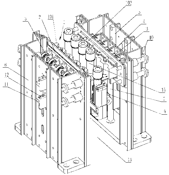
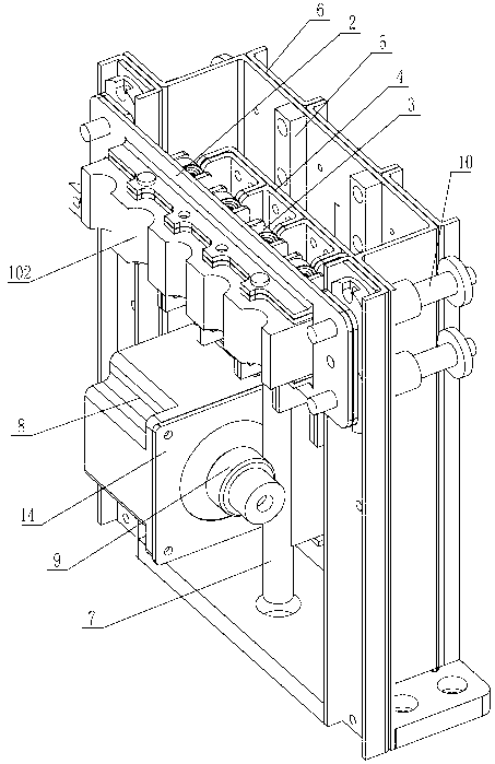
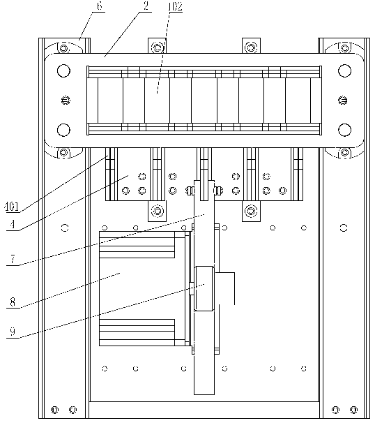
[0022] See figure 1 , figure 2 , the present invention includes a horizontally arranged test tube clamp 1, the test tube clamp 1 is fixedly connected to the mounting base 2, the other side of the mounting base 2 is fixed with a cam 3, and a cam guide plate 4 with a guide slope 401 is provided in front of the cam 3 , the cam 3 faces the guide slope 401, see image 3 , Figure 4 , the guide slope 401 is inclined towards the direction of the cam 3, the cam guide plate 4 is slidably supported on the frame 6 through the linear guide rail pair 5, the cam guide plate 4 is fixedly connected with the rack 7, and the motor 8 drives the gear 9 at the end of the shaft. The meshing transmission between 9 and the rack 7 drives the cam guide plate 4 to move up and down along the linear guide rail in the linear guide rail pair 5, and the guide slope 4...
PUM
 Abstract
Description
Claims
Application Information