Wire pay-off rack

A pay-off frame and wire rod technology, applied in the field of wire rod pay-off racks, can solve problems such as low work efficiency, affecting work efficiency, and wire chaos, and achieve the effect of reducing parking phenomena and improving work efficiency

Active Publication Date: 2013-08-28
张家港市中久金属制品有限公司
View PDF8 Cites 2 Cited by
  • Summary
  • Abstract
  • Description
  • Claims
  • Application Information

AI Technical Summary

Problems solved by technology

The disadvantage of this kind of wire pay-off rack is: during the drawing process of the wire drawing machine, the wire is often drawn out several times or even more than ten times at the same time, which will easily lead to the phenomenon of wire disorder; when the wire becomes disordered, the factory must Parking for processing greatly affects work efficiency
At present, in order to solve the problem of messy wires during the wire pay-off process, the factory needs to arrange additional workers next to the wire pay-off frame, and use manual assistance to pay off the wires, which not only wastes manpower, but also lowers work efficiency.

Method used


Image

  • Wire pay-off rack
  • Wire pay-off rack
  • Wire pay-off rack

Examples


Embodiment Construction

[0014] The present invention will be further described below in conjunction with the accompanying drawings and specific embodiments.

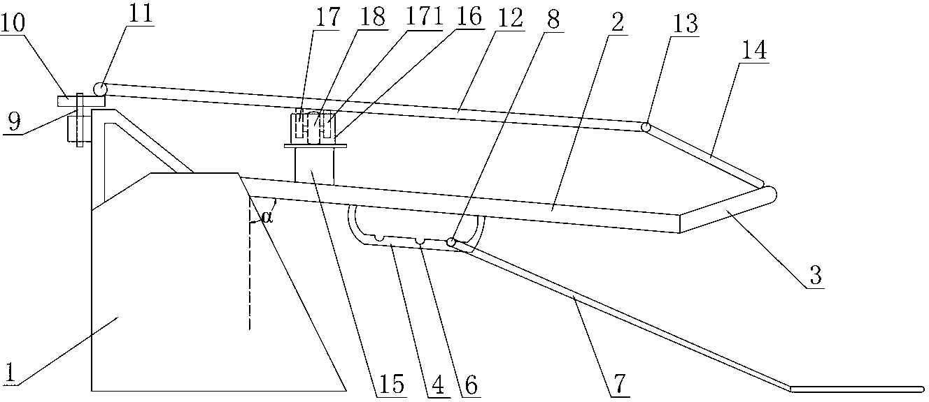
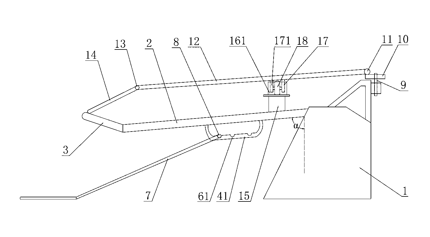
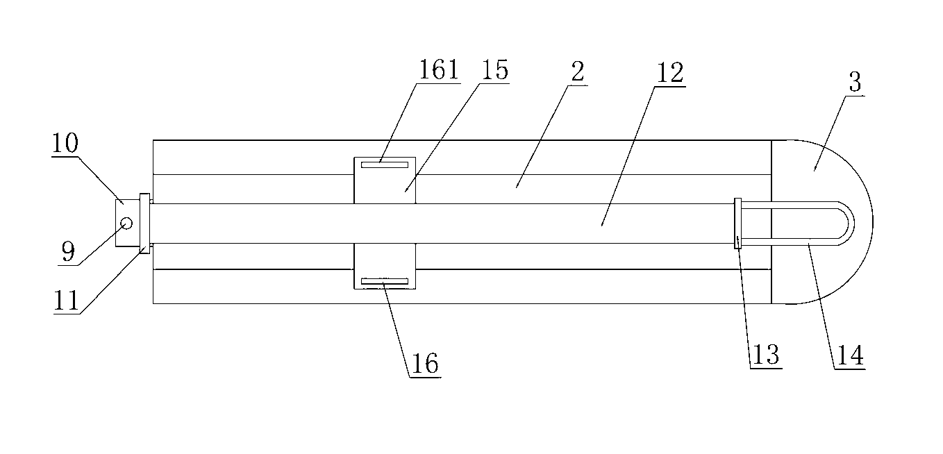
[0015] Such as figure 1 , figure 2 , image 3 As shown, a kind of wire rod pay-off frame described, comprises: frame 1, and the front end of frame 1 is installed with a wire-out front support 2 inclined downwards along the wire-out line direction, and the front-end support 2 of the wire rod The front end is fixed with a pay-off shelf 3 inclined upward along the wire pay-off direction. The angle of the pay-off shelf 3 is inclined upward to prevent the wire on the bracket 2 before the pay-off from sliding freely, and does not prevent the wire drawing machine from pulling the wire out; The upper end of the lower pendulum bar 7 is hinged to the bottom of the front bracket 2, and the lower end of the lower pendulum bar 7 hangs down to the ground along the wire unwinding direction and under its own gravity, so as to ensure the handover between the...


PUM


Abstract

The invention discloses a wire pay-off rack. The wire pay-off rack comprises a frame. A front end of the frame is provided with a wire pay-off front support which tilts down along a wire pay-off direction. A wire pay-off shelf which tilts up along the wire pay-off direction is fixed to a front end of the wire pay-off front support. An upper end of a lower swing rod is hinged to the bottom of the wire pay-off front support and a lower end of the lower swing rod is perpendicular to the ground along the wire pay-off direction under the action of self-gravity so that a vertical straight-line distance between the lower swing rod and a joint point of the wire pay-off front support and the wire pay-off shelf is greater than the diameter of a wire. A rear end of the frame is movably provided with a vertical rotation shaft. The vertical rotation shaft is fixed to a base. The base is hinged to a rear end of a compression rear rod. A front end of the compression rear rod is hinged to a rear end of a compression front rod. A front end of the compression front rod invariably presses against an upper surface of the wire pay-off shelf under the action of self-gravity. A compression rear rod rotation support mechanism is arranged between the compression rear rod and the wire pay-off front support. The wire pay-off rack realizes ordered loop-by-loop pay-off of wires in wire drawing.

Description

technical field [0001] The invention relates to the field of deep processing of metal wires, in particular to a wire pay-off stand in a wire drawing production line. Background technique [0002] In the metal products industry, wire rods are placed in a bundled state after being coiled into coils. The wire is usually placed on the wire pay-off rack during the drawing process of the wire drawing machine. The structure of the currently used wire pay-off rack is: including the frame, and at the front end of the rack is fixed a wire that is inclined upward along the wire pay-off direction. The linear pay-off rod is fixed with a lower swing rod on the frame below the pay-off rod. The disadvantage of this kind of wire pay-off rack is: during the drawing process of the wire drawing machine, the wire is often drawn out several times or even more than ten times at the same time, which will easily lead to the phenomenon of wire disorder; when the wire becomes disordered, the factory ...

Claims


Application Information

Patent Timeline
Patent Type & Authority Applications(China)
IPC IPC(8): B21C47/28B21C47/18
Inventor 蒋永华蒋卫华唐明
Owner 张家港市中久金属制品有限公司
Why Eureka
Try Eureka