Detection device and working method thereof

A detection device and detection unit technology, applied in mechanical depth measurement, printing, printing presses, etc., can solve problems such as inability to accurately detect pressure conditions, affecting the normal operation of equipment, limited contact area, etc., achieving low cost, easy maintenance, and response. Sensitive effect

Active Publication Date: 2012-10-03
天津长荣震德机械有限公司
View PDF4 Cites 3 Cited by
  • Summary
  • Abstract
  • Description
  • Claims
  • Application Information

AI Technical Summary

Problems solved by technology

However, due to the limited contact area between the pressure sensor and the wallboard, the reaction is often insensitive. Therefore, when foreign matter enters or paper accumulates between the upper and lower platforms, the pressure between the upper and lower platforms cannot be accurately detected, which often causes false alarms and affects the normal operation of the equipment.
At the same time, when the hot stamping process is done on the upper and lower platforms, the wall panels will often be thermally expanded and deformed due to the high temperature during the hot stamping process. At this time, the pressure sensor will also issue an overpressure alarm, causing false alarms, resulting in frequent machine stoppages and affecting work efficiency.

Method used


Image

  • Detection device and working method thereof
  • Detection device and working method thereof
  • Detection device and working method thereof

Examples


Embodiment 1

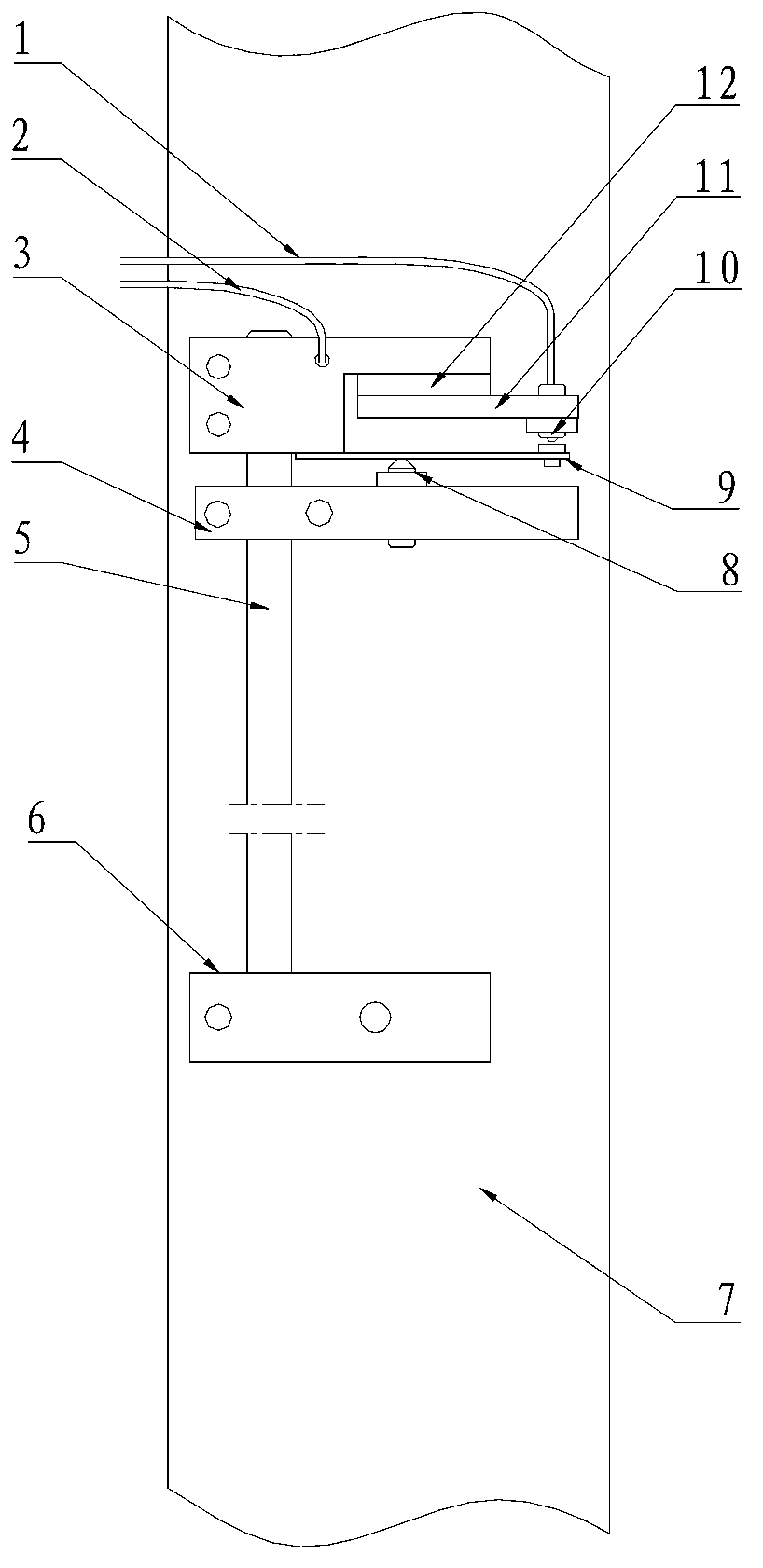
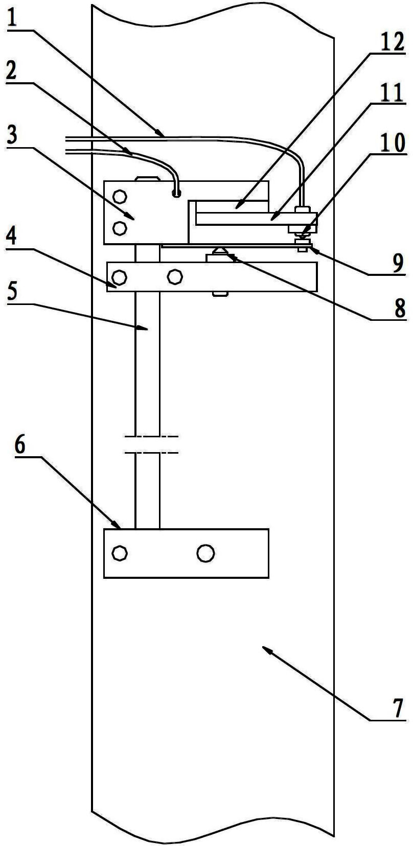
[0019] Such as figure 1 Shown: a detection device, including a sliding rod 5, a fixed block 6 and a set of detection units;

[0020] The detection unit includes a trigger block signal line 1, a spring leaf signal line 2, a connection block 3, an adjustment block 4, a top wire 8, a spring leaf 9, a positioning bead 10, a trigger block 11 and an insulating pad 12;

[0021] The fixing block 6 and the adjusting block 4 in the detection unit are fixedly connected to the wall panel 7;

[0022] The length of the sliding rod 5 is related to the deformation area of ​​the wall panel 7, and the part of the sliding rod 5 between the fixed block 6 and the adjusting block 4 is the easily deformable area of ​​the wall panel 7;

[0023] The adjusting block 4 and the connecting block 3 are each provided with an opening, one end of the sliding rod 5 is fixedly connected to the fixed block 6, and the other end passes through the openings of the adjusting block 4 and the connecting block 3 in turn; the co...

Embodiment 2

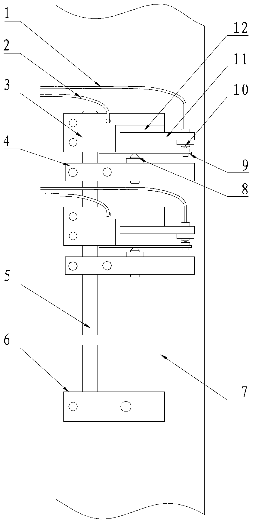
[0031] When the upper and lower platforms are used for hot stamping, the wall panel 7 will often undergo thermal expansion and deformation due to the high temperature during hot stamping. In order to accurately determine whether the alarm is caused by the thermal expansion and deformation of the wall panel 7, or the pressure on the upper and lower platforms increases instantaneously, the wall panel 7 occurs. For alarms caused by deformation, two sets of detection units need to be installed at this time. The specific plan is as follows:

[0032] Such as figure 2 As shown, a detection device includes a sliding rod 5, a fixed block 6 and two sets of detection units;

[0033] The detection unit includes a trigger block signal line 1, a spring leaf signal line 2, a connection block 3, an adjustment block 4, a top wire 8, a spring leaf 9, a positioning bead 10, a trigger block 11 and an insulating pad 12;

[0034] The fixing block 6 and the adjusting block 4 in the detection unit are fi...


PUM


Abstract

The invention relates to a detection device and a working method thereof. The detection device comprises a slide bar, a fixed block and a detection unit and can overcome the defects of the prior art, the deformation of a wallboard due to the fact that the pressure between an upper platform and a lower platform instantaneously exceeds a set value and the deformation of the wallboard due to thermal expansion in a gold stamping process can be respectively detected, a positioning ball is touched by a leaf spring, and then a signal wire is conducted to send out an overpressure alarm. The detection device and the working method thereof disclosed by the invention have the characteristics of high reaction sensitivity, accurate alarming and easiness in realization.

Description

Technical field [0001] The invention is suitable for printing machinery, and is particularly suitable for detection devices and working methods of printing machinery. Background technique [0002] With the continuous improvement and improvement of various functions of printing equipment, many detection and alarm devices are often installed on printing equipment to ensure the safety of personnel operating the equipment and the normal operation of the equipment itself. Therefore, the sensitivity of the detection and alarm devices and the accuracy of alarms It seems very important. [0003] The upper and lower platforms of the printing equipment are installed between the two wall panels, and the die-cutting and hot stamping processes of the printed products are realized through the continuous pressing of the upper and lower platforms. When foreign matter enters or stacks of paper between the upper and lower platforms, the pressure of the upper and lower platforms will instantly excee...

Claims


Application Information

Patent Timeline
Patent Type & Authority Applications(China)
IPC IPC(8): B41F33/00G01B5/18
Inventor 彭章波
Owner 天津长荣震德机械有限公司
Why Eureka
Try Eureka