Direct transmission type milling machine

A transmission type and milling machine technology, which is applied in the direction of driving devices, metal processing machinery parts, metal processing equipment, etc., can solve the problems of high energy consumption of multi-stage gear transmission, large loss of motor power, easy damage of clutches, etc., and achieves easy promotion, The effect of increasing the rotation speed and reducing the probability of failure

Inactive Publication Date: 2013-08-28
CHONGQING BAIJI SIXING DIE CASTING
View PDF8 Cites 0 Cited by
  • Summary
  • Abstract
  • Description
  • Claims
  • Application Information

AI Technical Summary

Problems solved by technology

[0002]At present, the milling machine used includes the headstock, speed change mechanism, operating mechanism, ordinary motor, coupling, etc., wherein the speed change mechanism is a set of complex multi-stage The gear mechanism has a relatively complex structure, and the clutch is easily damaged when it is stopped at high speed, and the failure rate is extremely high; secondly, due to the limitation of multi-stage gear transmission, the maximum speed of the milling machine spindle can reach 1800 rpm; thirdly, multi-stage gear transmission consumes energy Larger motor power loss

Method used


Image

  • Direct transmission type milling machine

Examples


Embodiment 1

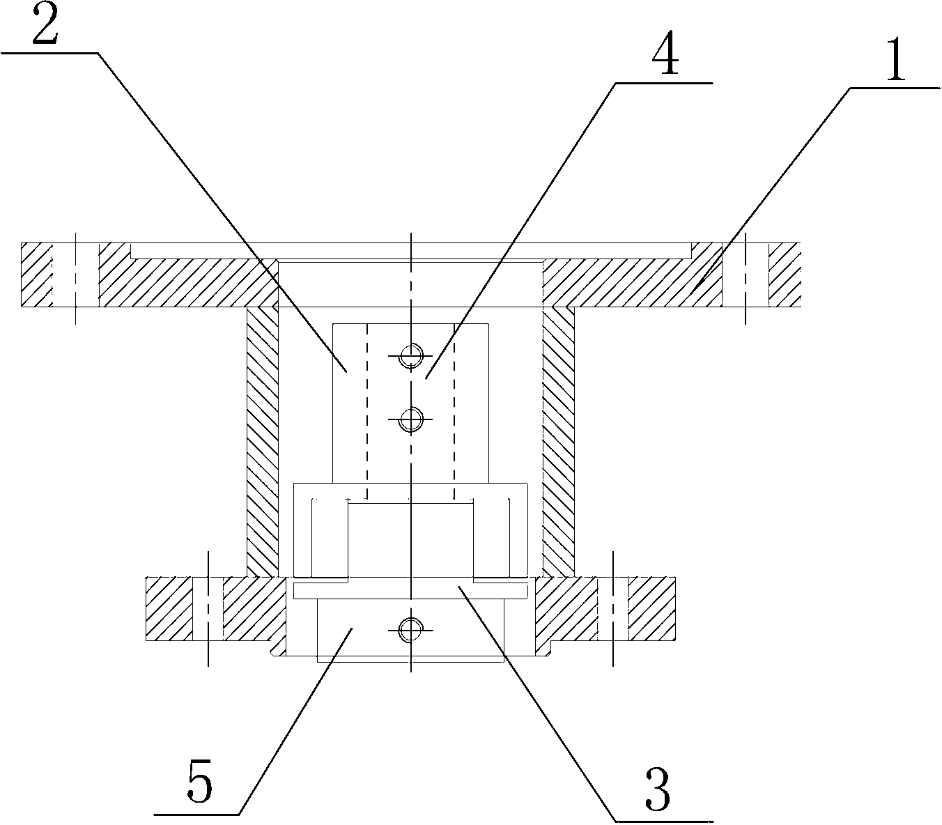
[0013] Embodiment 1: refer to figure 1 , a direct-drive milling machine, including a main shaft 5, a 30KW frequency conversion motor, an upper connection sleeve 2 and a lower connection sleeve 3 are installed on the base 1 of the frequency conversion motor, and the upper and lower connection sleeves are fitted and fastened by the concave and convex parts .

[0014] Have screw hole on the cover body of upper connection cover 2, have flat key keyway in the cover. The 4 ends of the output shaft of the variable frequency motor are inserted into the flat key in the upper connecting sleeve 2 to connect, and then fastened with the upper connecting sleeve 2 by bolts.

[0015] Have screw hole on the cover body of lower connection cover 3, have flat key keyway in the cover. The end of the main shaft 5 is inserted into the flat key in the lower connecting sleeve 3 for connection, and then fastened with the lower connecting sleeve 3 by bolts.

Embodiment 2

[0016] Embodiment 2: The variable frequency motor in Embodiment 1 is replaced by a servo motor, and other features are the same as Embodiment 1.


PUM


Abstract

The invention discloses a direct transmission type milling machine. The direct transmission milling machine comprises a main shaft and a variable-speed motor; two connecting sleeves embedded with each other are arranged in a seat of the variable-speed motor; an output shaft of the variable-speed motor is in key joint with one connecting sleeve, and the main shaft is in key joint with the other connecting sleeve; and a fixing device which prevents the main shaft and the output shaft of the variable-speed motor from sliding in the axial direction is arranged on the connecting sleeves. The milling machine disclosed by the invention is simple in structure, low in energy consumption, low in failure rate, high in operability and easy to popularize.

Description

technical field [0001] The invention relates to a direct-drive milling machine, which belongs to the technical field of machine tools. Background technique [0002] At present, the milling machine used includes a spindle box, a speed change mechanism, an operating mechanism, an ordinary motor, a shaft coupling, etc., and the speed change mechanism is a set of complex multi-stage gear mechanisms, the structure is relatively complicated, and the clutch is very easy when starting at high speed. damage, the failure rate is extremely high; secondly, due to the limitation of multi-stage gear transmission, the speed of the milling machine spindle can reach up to 1800 rpm; thirdly, multi-stage gear transmission consumes a lot of energy and the motor power loss is large. [0003] Contents of the invention [0004] The present invention aims to provide a direct-drive milling machine with less energy consumption, low failure rate and simple structure. [0005] The object of the pre...

Claims


Application Information

Patent Timeline
Patent Type & Authority Applications(China)
IPC IPC(8): B23Q5/10
CPCY02P70/10
Inventor 左麟曹彦
Owner CHONGQING BAIJI SIXING DIE CASTING
Why Eureka
Try Eureka