Auxiliary plate spring support

A technology of sub-plates and arc-shaped surfaces, applied in the direction of springs, leaf springs, springs/shock absorbers, etc., can solve the problems of unfavorable frame longitudinal beam hole position standardization, poor frame longitudinal beam processing technology, etc., to achieve hole Position, improve the effect of processing technology

Active Publication Date: 2013-08-28
DONGFENG MOTOR CORP HUBEI
View PDF7 Cites 0 Cited by
  • Summary
  • Abstract
  • Description
  • Claims
  • Application Information

AI Technical Summary

Problems solved by technology

[0004] The purpose of the present invention is to overcome the problems of poor processing technology of the frame longitudinal beam and unfavorable frame longitudinal beam hole positio

Method used


Image

  • Auxiliary plate spring support
  • Auxiliary plate spring support
  • Auxiliary plate spring support

Examples


Embodiment Construction

[0015] The present invention will be further described in detail below in conjunction with the accompanying drawings and specific embodiments.

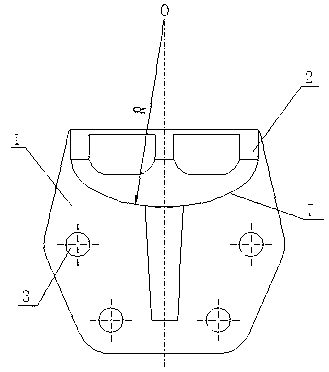
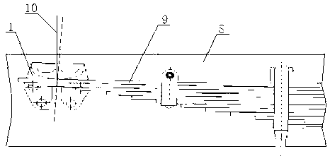
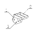
[0016] see Figure 3-Figure 5 , a secondary leaf spring bracket, which is connected to the frame longitudinal beam 8 by bolts or rivets, including a bracket main body 1 and a limit block 2, the bottom of the bracket body 1 is provided with a connecting hole 3, and the limit block The arc curved surface on the block 2 is a support curved surface, and the support curved surface is a curved surface in contact with the auxiliary leaf spring 9 and the auxiliary leaf spring support; the support curved surface is formed by connecting the arc curved surface I4, the arc curved surface II5 and the arc curved surface III6 , the radius of the arc surface I4 is R1, the center of the arc surface I4 is O1, the radius of the arc surface III6 is R2, the center of the arc surface III6 is O2, the circle center O1 of the arc surface I4 and the arc surfac...


PUM


Abstract

An auxiliary plate spring support comprises a support body (1) and a limiting retainer (2). Connecting holes (3) are arranged on the lower portion of the support body (1), a circular arc curved surface on the lower portion of the limiting retainer (2) is a supporting curved surface contacting with an auxiliary plate spring (9), the supporting curved surface is formed by connecting a circular arc curved surface I (4), a circular arc curved surface II (5) and a circular arc curved surface III (6), circular arc centers of the circular arc curved surface I (4) and the circular arc curved surface III (6) deviate from a symmetric center surface of the auxiliary plate spring support, the radius of the circular arc curved surface I (4) is equal to that of the circular arc curved surface III (6), the circular arc curved surface I (4) and the circular arc curved surface III (6) are symmetric relatively to the symmetric center surface of the auxiliary plate spring support, a slant angle alpha of the circular arc curved surface I (4) is equal to a slant angle beta of the circular arc curved surface III (6) and equal to a fully-loaded slant angle delta of the auxiliary plate spring (9), and the circular arc center of the circular arc curved surface II (5) is positioned on the symmetric center surface of the auxiliary plate spring support. By the auxiliary plate spring support, hole position standardization is realized.

Description

technical field [0001] The invention relates to a structural design of an auxiliary leaf spring bracket of an automobile leaf spring, more specifically relates to an auxiliary leaf spring bracket, and belongs to the technical field of truck suspension systems. Background technique [0002] The existing single rear axle of trucks has a large change in axle load from no-load to full-load. Generally, the rear suspension adopts the main plate spring + auxiliary leaf spring configuration; the current typical main and auxiliary leaf spring structure, the auxiliary leaf spring is arranged above the main plate spring, An auxiliary leaf spring support is arranged above the two ends of the auxiliary leaf spring, and the auxiliary leaf spring support is fixed on the longitudinal beam of the vehicle frame; the above-mentioned structure has simple process, mature design method and strong versatility, and is adopted by most automobile manufacturers. When the axle load of the rear axle is ...

Claims


Application Information

Patent Timeline
IPC IPC(8): B60G11/10
Inventor 盛其军丁小甦叶爱凤张光哲易建武
Owner DONGFENG MOTOR CORP HUBEI
Why Eureka
Try Eureka