Building temperature cycle control system

A temperature cycle and control system technology, applied in the field of housing construction, to achieve the effect of saving electric energy and reducing electricity consumption

Inactive Publication Date: 2013-08-28
赖正伦
View PDF11 Cites 1 Cited by
  • Summary
  • Abstract
  • Description
  • Claims
  • Application Information

AI Technical Summary

Problems solved by technology

[0004] The technical problem to be solved by the present invention is to solve the disadvantages of the prior art indoor temperature adjustment only by air conditioners, thereby providing a house temperature cycle control system with simple structure, safe use and low energy consumption rate

Method used


Image

  • Building temperature cycle control system

Examples


Embodiment Construction

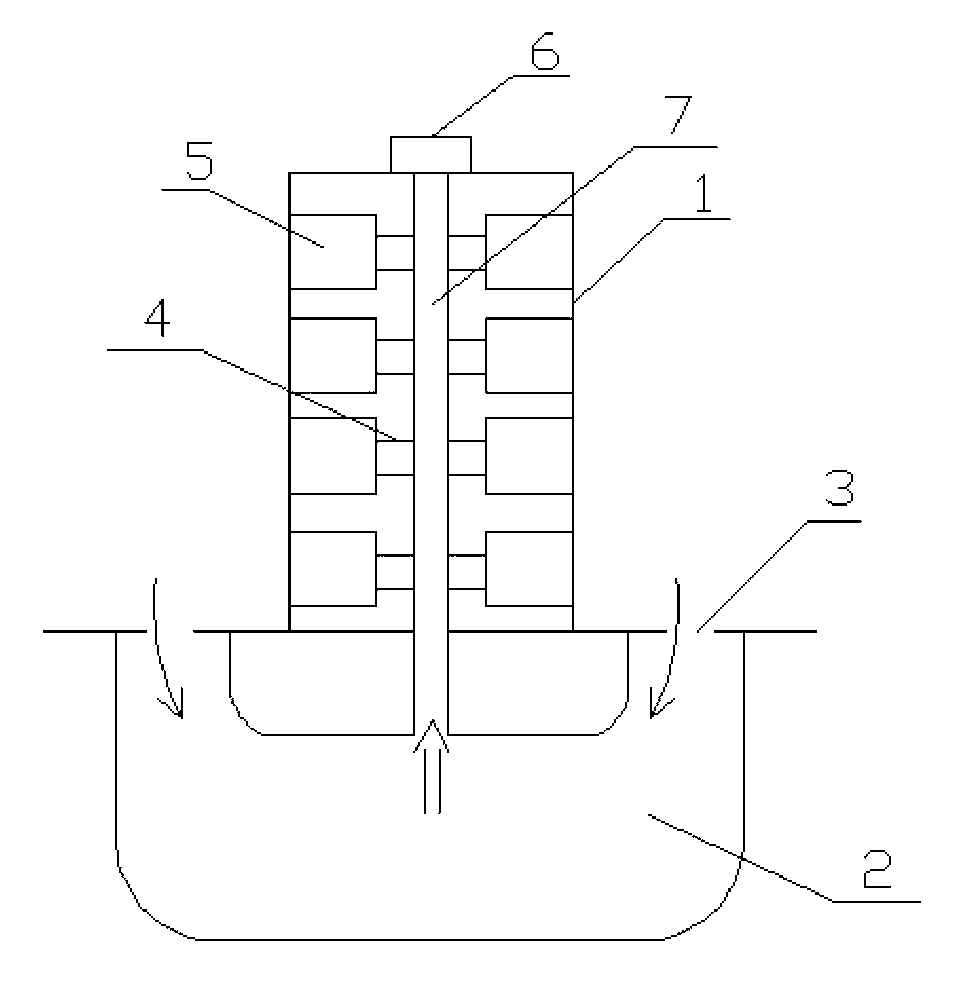
[0015] Please refer to figure 1 As shown, a house temperature cycle control system of the present invention includes a building body 1, a large ventilation channel 2 is opened under the building body 1, and several ventilation openings 3 are arranged between the ventilation channel 2 and the ground. The body 1 is provided with an air duct 7 that runs through the entire building body 1 , the air duct 7 communicates with the air duct 2 , and the building body 1 is provided with several room units 5 .

[0016] Wherein, each room unit 5 is connected with the ventilation channel 7, and when the air rises in the ventilation channel 7, the air through the heat conversion will enter into each room unit 5, thereby realizing the exchange of cold air and hot air. cycle.

[0017] A blower 4 is placed in each room unit 5 , and the air in the ventilation channel 7 is sucked into the room unit 5 by the blower 4 .

[0018] A high-power fan 6 is arranged at the vent at the top of the buildin...


PUM


Abstract

The invention discloses a building temperature cycle control system. The building temperature cycle control system comprises a building body. A large ventilation channel is formed below the building body. A plurality of ventilation openings are formed between the ventilation channel and the ground. A ventilating way penetrating through the building body is formed inside the building body and communicated with the ventilation channel. A plurality of room units are arranged in the building body. According to the building temperature cycle control system, the large ventilation channel formed below the building body is utilized for achieving air cold and thermal cycle among the room units in the building body, a traditional constant temperature pattern in the past is abandoned, a uniform low-consumption constant temperature cycle system is achieved, use requirements of residents can be met, electricity consumption of the residents of each household is reduced greatly, and electricity energy is saved. Thus, the building temperature cycle control system conforms to the standard of energy conservation and emission reduction.

Description

technical field [0001] The invention relates to a house temperature circulation control system, which belongs to the field of house construction. Background technique [0002] In daily life, air conditioners have been widely used in every household, and air conditioners are a unit used to provide space areas (generally closed) to deal with air temperature changes. Its function is to adjust the parameters such as temperature, humidity, cleanliness and air flow rate of the air in the room (or closed space, area) to meet the requirements of human comfort or technological process, but the air conditioner itself has a large working rate, and in When working, it often needs to consume a large amount of electric energy, and long-term use will greatly increase the consumption of residents. [0003] And people easily get air-conditioning disease in air-conditioning room for a long time, influence people's health, so existing indoor use air-conditioning to regulate indoor ...

Claims


Application Information

Patent Timeline
Patent Type & Authority Applications(China)
IPC IPC(8): F24F7/06F25B27/00
Inventor 赖正伦
Owner 赖正伦
Why Eureka
Try Eureka