High-low temperature circulating device for thermal cycle adsorption separation device

A high-low temperature cycle, adsorption and separation technology, applied in the field of thermonuclear fusion, can solve the problems of low efficiency and poor effect, and achieve the effect of increasing the speed of temperature change, improving the efficiency of heating and cooling, and ensuring uniformity

Pending Publication Date: 2020-08-25
MATERIAL INST OF CHINA ACADEMY OF ENG PHYSICS
View PDF7 Cites 2 Cited by
  • Summary
  • Abstract
  • Description
  • Claims
  • Application Information

AI Technical Summary

Problems solved by technology

[0005] The purpose of the present invention is to provide a high and low temperature cycle device for thermal cycle separation and adsorption devices for the problem of poor effect and low efficiency when heating with an electric furnace or a heating plate when the thermal cycle adsorption method is implemented in the prior art

Method used


Image

  • High-low temperature circulating device for thermal cycle adsorption separation device
  • High-low temperature circulating device for thermal cycle adsorption separation device
  • High-low temperature circulating device for thermal cycle adsorption separation device

Examples


Embodiment 1

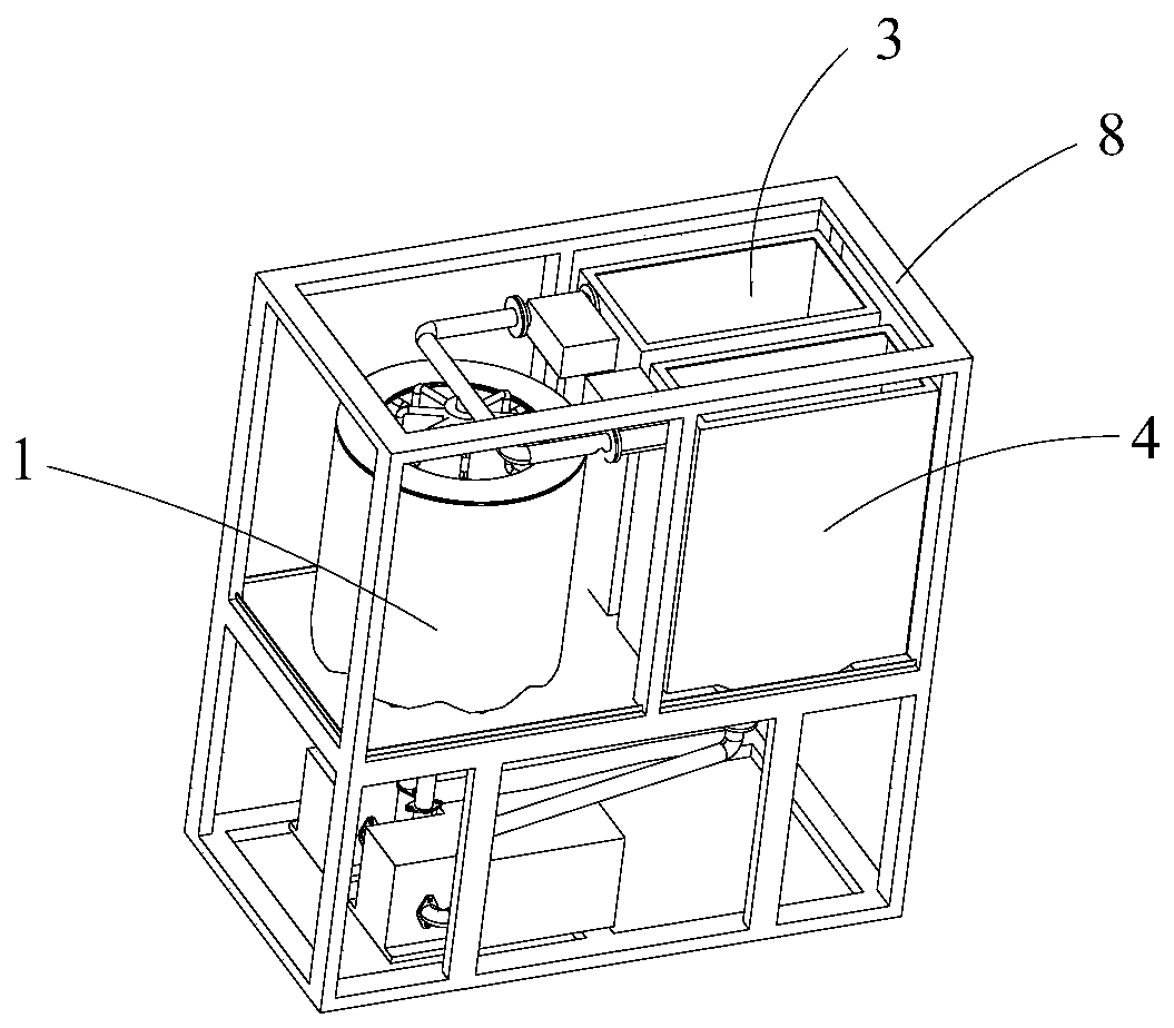
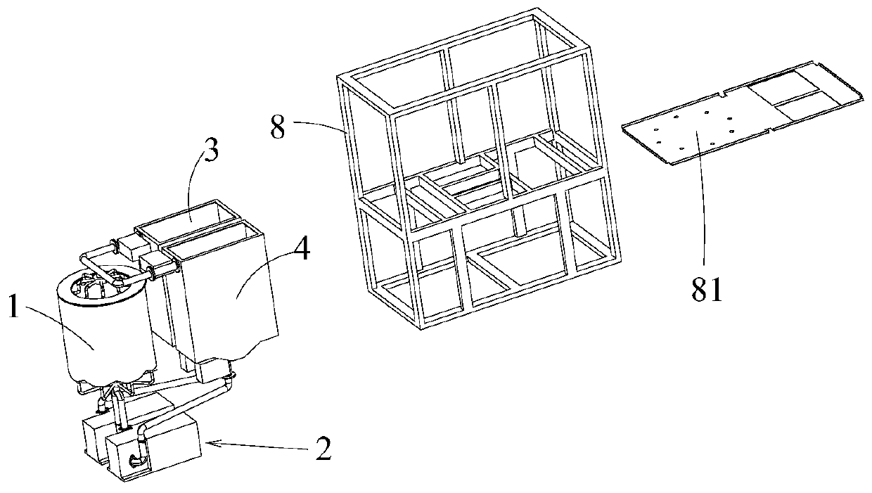
[0059] A high and low temperature cycle device for thermal cycle adsorption separation device, such as Figure 1-4 As shown, it includes an oil bath 1, an oil pump 2, a first oil tank 3 and a second oil tank 4; the oil bath 1 is used to accommodate a separation column, and the oil bath 1 is provided with an oil inlet and an oil outlet; The oil inlet of the oil bath 1 is arranged at the bottom of the oil bath 1 , and the oil outlet of the oil bath 1 is arranged at the top of the oil bath 1 .

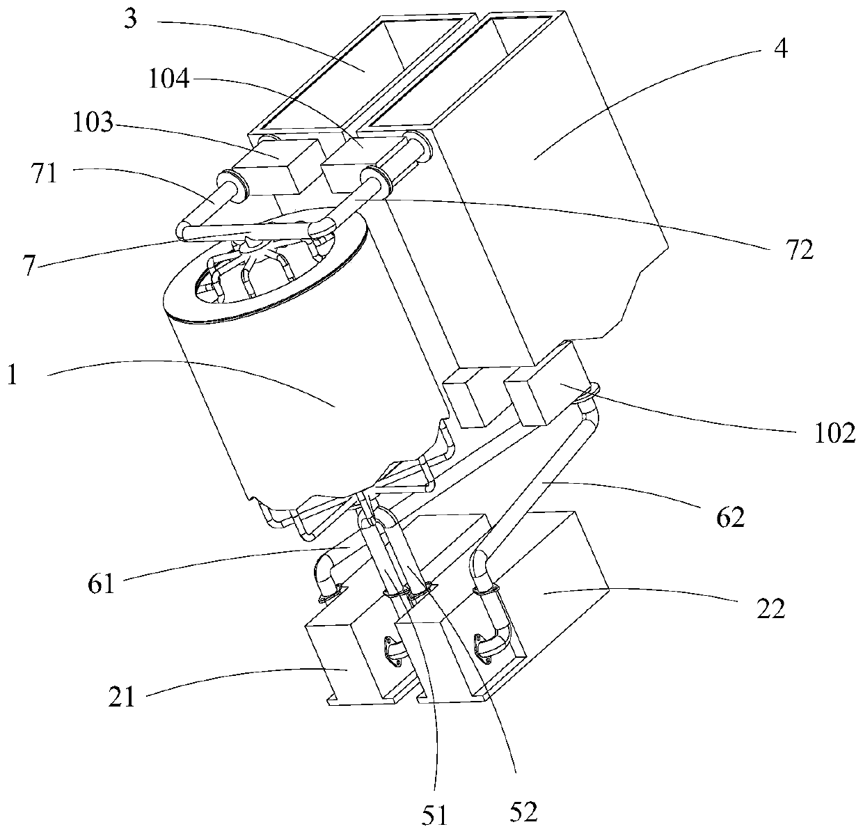
[0060] The outlet of the oil pump 2 communicates with the oil inlet of the oil bath 1 through the oil inlet main pipe 5; the oil pump 2 includes a first oil pump 21 and a second oil pump 22; the oil inlet main pipe 5 includes a first oil inlet main pipe 51 and the second oil inlet supervisor 52;

[0061] The outlet of the first oil pump 21 communicates with the oil inlet of the oil bath 1 through the first oil inlet main pipe 51, and the inlet of the first oil pump 21 communicates with t...

Embodiment 2

[0079] Present embodiment improves oil bath 1 on the basis of embodiment 1, as Figure 5 , Figure 6 The oil bath 1 shown is in the shape of a hollow cylindrical ring. That is, the oil bath 1 includes a cylindrical outer wall 15, a cylindrical inner wall 16, an annular bottom wall 13 and an annular top wall 14; the upper and lower ends of the cylindrical outer wall 15 are respectively connected to the annular top wall 14 and the annular top wall The outer side of the annular bottom wall 13; the cylindrical inner wall 16 is located in the cylindrical outer wall 15, and the upper and lower ends of the cylindrical inner wall 16 are respectively connected to the annular top wall 14 and the annular bottom wall 13 inside.

[0080] Several oil inlet branch pipes 11 are arranged between the oil inlet main pipe 5 and the oil bath 1, and the several oil inlet branch pipes 11 are uniformly connected to the annular bottom wall 13 of the oil bath. Several oil outlet branch pipes 12 are ...

Embodiment 3

[0084] The difference between this embodiment and embodiment 1 is that, as Figure 8 As shown, the position of the first valve 101 and the second valve 102 is set to the common rear end of the first oil pump 21 and the second oil pump 22 , and the main valve 107 is set on the main oil pipe 5 . Through the control of multiple valves, the oil pump receives less heat and cold impact when it is not working, which can improve the service life of the oil pump and maintain the stability of the oil pump.


PUM


Abstract

The invention relates to the field of thermonuclear fusion, in particular to separation of hydrogen isotope gas, and particularly relates to a high-low temperature circulating device for a thermal cycle adsorption separation device. The high-low temperature circulating device comprises an oil bath, an oil pump, a first oil tank and a second oil tank. The oil bath is used for accommodating a separation column; the oil pump is used for pumping oil in the first oil tank or the second oil tank to the oil bath; a valve is arranged at the inlet end and / or the outlet end of the oil pump; the oil outlet of the oil bath is provided with a first oil outlet main pipe and a second oil outlet main pipe, the first oil outlet main pipe is communicated with the inlet of the first oil tank, and the secondoil outlet main pipe is communicated with the inlet of the second oil tank; the first oil outlet main pipe is provided with a third valve, and the second oil outlet main pipe is provided with a fourthvalve. The temperature uniformity of the separation column is guaranteed, and cold and hot circulation of flowing media in the oil bath is achieved through the high-temperature oil tank, the low-temperature oil tank and the oil pump. The separation effect and the efficiency are improved.

Description

technical field [0001] The invention relates to the field of thermonuclear fusion, in particular to the separation of hydrogen isotope gas, and in particular to a high-low temperature cycle device used in a thermal cycle adsorption separation device. Background technique [0002] Thermal Cycling Absorption Process (TCAP) was first proposed theoretically and conceptually by M.W. Lee of Savannah River Laboratory, and was formally established and put into operation in 1994. The TCAP system is mainly composed of two parts, one is a chromatographic separation column filled with palladium-loaded materials, and the other is an empty column (reflux column), and the upper ends of the two columns are connected by a valve; during separation, the palladium-loaded column is at half-cycle high temperature and half-cycle low temperature in the heating and cooling cycle. In addition to being able to easily separate hydrogen-deuterium and hydrogen-tritium, TCAP can also separate deuterium-t...

Claims


Application Information

Patent Timeline
Patent Type & Authority Applications(China)
IPC IPC(8): B01D59/26
CPCB01D59/26
Inventor 邓立陈长安黄国强胡俊杨莞陈克琳姚勇王劲川陈俊光陈军
Owner MATERIAL INST OF CHINA ACADEMY OF ENG PHYSICS
Why Eureka
Try Eureka