Circuit and method for measuring voltage transformer voltage coefficient

A technology of voltage transformers and voltage coefficients, applied in the direction of measuring electric variables, measuring devices, instruments, etc., can solve the problems of electric field shielding design and manufacturing difficulties, shielding error increase, etc.

Active Publication Date: 2013-08-28
ELECTRIC POWER RES INST OF GUANGDONG POWER GRID
View PDF9 Cites 11 Cited by
  • Summary
  • Abstract
  • Description
  • Claims
  • Application Information

AI Technical Summary

Problems solved by technology

When the voltage exceeds 110kV, the design and manufacture of electric field shielding are very difficult, and imperfect shielding will significantly increase the shielding error, thus limiting the application of series-parallel addition and series addition in ultra-high voltage and ultra-high voltage

Method used


Image

  • Circuit and method for measuring voltage transformer voltage coefficient
  • Circuit and method for measuring voltage transformer voltage coefficient
  • Circuit and method for measuring voltage transformer voltage coefficient

Examples


Embodiment Construction

[0043] Hereinafter, the present invention will be further described with reference to the accompanying drawings.

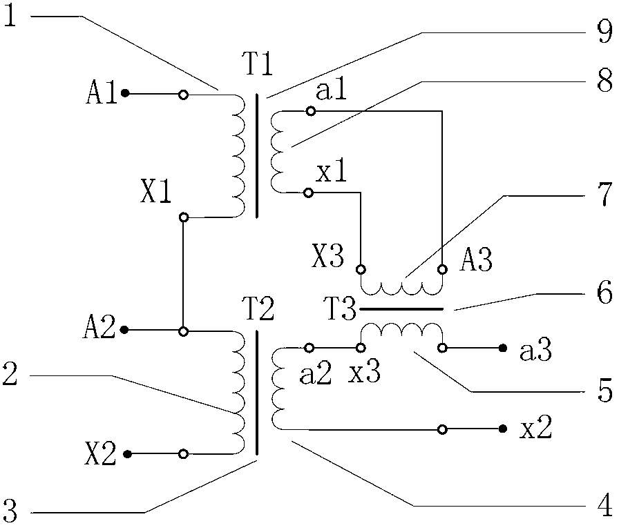
[0044] Such as figure 1 As shown, the passive linear circuit embodiment of the present invention is composed of a single-stage voltage transformer with the same rated voltage, a first single-stage voltage transformer T1, a second single-stage voltage transformer T2, and an isolation transformer T3. The first single-stage voltage The rated transformation ratio of the transformer T1 and the second single-stage voltage transformer T2 are both equal to K, and the rated transformation ratio of the isolation transformer T3 is equal to 1. The primary winding end X1 of the first single-stage voltage transformer T1 is connected to the primary winding start end A2 of the second single-stage voltage transformer T2. The secondary output of the first single-stage voltage transformer T1 is used as the primary input of the isolation transformer T3. The secondary winding end x1 of ...


PUM


Abstract

The invention relates to a circuit for measuring a voltage transformer voltage coefficient, and further relates to a method for measuring the voltage transformer voltage coefficient through the circuit. The circuit for measuring the voltage transformer voltage coefficient comprises a first single-stage voltage transformer (T1), a second single-stage voltage transformer (T2) and a passive linear circuit composed of an isolation transformer (T3). Both the rated transformation ratio of the first single-stage voltage transformer (T1) and the rated transformation ratio of the second single-stage voltage transformer (T2) are equal to K; the rated transformation ratio of the isolation transformer (T3) is equal to 1; a primary low-voltage terminal (X1) of the first single-stage voltage transformer (T1) is connected with a primary high-voltage terminal A2 of the second single-stage voltage transformer (T2); a secondary high-voltage terminal a1 of the first single-stage voltage transformer (T1) is connected with a primary high-voltage terminal A3 of the isolation transformer (T3); a secondary low-voltage terminal x1 of the first single-stage voltage transformer (T1) is connected with a primary low-voltage terminal X3 of the isolation transformer (T3); a secondary low-voltage terminal x3 of the isolation transformer (T3) is connected with a secondary high-voltage terminal a2 of the second single-stage voltage transformer (T2). According to the circuit and method for measuring the voltage transformer voltage coefficient, the effect of shielding errors of a voltage transformer on a series addition line can be overcome, and power frequency voltage addition can be effectively used in a 220 kV high-voltage interval and can even be used in a 330kV-1000kV extra-high-voltage interval.

Description

Technical field [0001] The invention relates to a circuit for measuring the voltage coefficient of a voltage transformer. The invention also relates to a method for measuring the voltage coefficient of a voltage transformer by using the line. Background technique [0002] The power frequency voltage proportional value needs to be derived according to the definition of the ratio of metrology. The process requires two test steps. One is to compare the two voltage values ​​to determine their degree of similarity. It is expressed by ratio error and phase error. The technique is precision measurement of errors; the second is to add several voltages with the same nominal value to obtain the multiple relationship of the two voltages. Its core technology is stacked frequency voltage. Usually these two technologies are collectively referred to as power frequency voltage addition technology. At present, the power frequency voltage addition with voltage lower than 2kV generally uses the ...

Claims


Application Information

Patent Timeline
Patent Type & Authority Applications(China)
IPC IPC(8): G01R35/02
Inventor 宋强胡嘉孙卫明潘峰
Owner ELECTRIC POWER RES INST OF GUANGDONG POWER GRID
Why Eureka
Try Eureka