
Automotive antenna

A car antenna and antenna technology, which is applied in the electronic field, can solve problems such as difficulty in exerting the best reception effect of the antenna, inability to reach the tilt angle, and inability to rotate the antenna, etc., and achieve the effects of facilitating signal processing, prolonging service life, and strong practicability

Inactive Publication Date: 2013-08-28
莫志强
View PDF1 Cites 2 Cited by
  • Summary
  • Abstract
  • Description
  • Claims
  • Application Information

AI Technical Summary

Problems solved by technology

[0002] The second industrial revolution brought human civilization into the age of electrical appliances, and electronic equipment has also become household names. After more than half a century of development, a series of products in the electronic field have increasingly enriched our production and life. With the development of automobiles Popularity, the car antenna is an indispensable and important part of it. The car antenna on the market is composed of a simple base and an antenna pole, which can no longer meet the multi-directional requirements of modern society. The application number is CN201220358860.9, which discloses a car antenna , the car antenna includes a base, a screw, a gasket, a spring sheet, a screw and an antenna rod, the screw is covered with a connecting rod, and the connecting rod is provided with a ratchet, and after the screw is threaded with the antenna rod, The ratchet is just set in the tooth groove of the antenna rod; the screw is provided with a limiting rib, the base is provided with a connecting shaft, and a limiting groove is provided at both ends of the bottom side of the connecting shaft, and the base passes through The connecting shaft is connected with the screw rod in rotation, so that the limiting rib is limited in the limiting groove. The utility model has a simple structure, which makes the antenna rod not easy to loosen, improves the reliability of the antenna receiving signal transmission, and enhances the reliability of the automotive antenna. Waterproof function, but the car antenna can not listen to the radio while positioning the car, and the antenna cannot be rotated to achieve different tilt angles, so it is difficult to play the best reception effect of the antenna

Method used


Image

  • Automotive antenna

Examples


Embodiment Construction

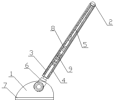
[0013] Such as figure 1 As shown, a car antenna includes a base 1 and an antenna rod 2, and the antenna rod 2 includes a sound

[0014] frequency antenna 3 and GPS antenna 4, the audio frequency antenna 3 and GPS antenna 4 are electrically connected to the automobile system, the antenna rod 2 is provided with an insulating slot 5, and the audio frequency antenna 3 and GPS antenna 4 are fixedly connected to the insulating socket On the slot 5, a rotating part 6 is fixed below the antenna rod 2, and the rotating part 6 is threadedly connected with the base 1. The present invention can listen to the radio while positioning the car, and the antenna can rotate. Different inclination angles can be achieved, the best receiving effect of the antenna can be exerted, the utility model has strong practicability, and is suitable for popularization and use.

[0015] It is worth noting that a waterproof pad 7 is provided above the base 1, the waterproof pad prevents the base from entering ...


PUM


Abstract

The invention discloses an automotive antenna which comprises a base and an antenna rod, wherein the antenna rod comprises an audio antenna and a global position system (GPS) antenna, wherein the audio antenna and the GPS antenna are electrically connected with the automobile system; an insulating slot is formed in the antenna rod; the audio antenna and the GPS antenna are fixedly connected to the insulating slot; a rotating piece is fixed below the antenna rod; and the rotating piece is in threaded connection with the base. According to the mode, the automobile can be positioned, the broadcast can be listened, the antenna can rotate, different inclined angles can be achieved, the optimized reception effect of the antenna is exerted, and the automotive antenna is high in practicability and suitable for popularization and application.

Description

technical field [0001] The invention relates to the field of electronics, in particular to an automotive antenna. Background technique [0002] The second industrial revolution brought human civilization into the age of electrical appliances, and electronic equipment has also become household names. After more than half a century of development, a series of products in the electronic field have increasingly enriched our production and life. With the development of automobiles Popularity, the car antenna is an indispensable and important part of it. The car antenna on the market is composed of a simple base and an antenna pole, which can no longer meet the multi-directional requirements of modern society. The application number is CN201220358860.9, which discloses a car antenna , the car antenna includes a base, a screw, a gasket, a spring sheet, a screw and an antenna rod, the screw is covered with a connecting rod, and the connecting rod is provided with a ratchet, and afte...

Claims


Application Information

Patent Timeline
IPC IPC(8): H01Q3/02H01Q21/30H01Q1/12
Inventor 莫志强
Owner 莫志强
Learn More