Manufacturing method of optical film, polarizing plate, and image display device

A manufacturing method and technology for optical films, applied in chemical instruments and methods, optics, optical components, etc., can solve problems such as reduced manufacturing efficiency, defects in surface shape or optical characteristics, damage to mechanical strength and optical characteristics of optical films, etc. The effect of manufacturing efficiency

Active Publication Date: 2015-09-23
SUMITOMO CHEM CO LTD
View PDF9 Cites 0 Cited by
  • Summary
  • Abstract
  • Description
  • Claims
  • Application Information

AI Technical Summary

Problems solved by technology

In terms of resin residue, in the continuous production of an optical film in which a resin layer is continuously formed on a long base film, continuous defects (resin adhesion to the surface of the optical film, defects in surface shape or optical properties, etc.)
In addition, when resin remains, removing it for cleaning will greatly reduce manufacturing efficiency
[0006] On the other hand, as a method of preventing resin residue, it is conceivable to add a release agent to the coating liquid forming the coating layer, or to apply a release agent on the surface of the mold in advance, but the addition of a release agent may damage the optical quality. Film mechanical strength, optical properties

Method used


Image

  • Manufacturing method of optical film, polarizing plate, and image display device
  • Manufacturing method of optical film, polarizing plate, and image display device
  • Manufacturing method of optical film, polarizing plate, and image display device

Examples


Embodiment 1

[0101] The following components were mixed to prepare an ultraviolet curable coating liquid.

[0102] Ultraviolet curable resin: 60 parts by weight of pentaerythritol triacrylate and 40 parts by weight of polyfunctional urethane acrylate (reaction product of hexamethylene diisocyanate and pentaerythritol triacrylate)

[0103] · "Lucirin TPO" (manufactured by BASF Corporation, chemical name: 2,4,6-trimethylbenzoyldiphenylphosphine oxide) 5 parts by weight

[0104] • Diluting solvent: 100 parts by weight of ethyl acetate.

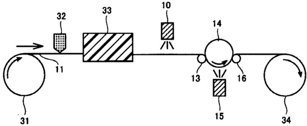
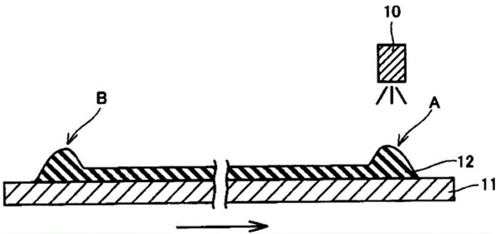
[0105] Apply the above-mentioned coating solution to a triacetyl cellulose (TAC) film (base film) with a thickness of 80 μm by gravure coating to form a coating layer, and obtain a laminate of the base film and the coating layer [coating process] ]. After drying the obtained laminated body using a drying oven, an ultraviolet irradiation device having a comb-shaped filter having a plurality of comb-shaped teeth whose width gradually narrows in the direction ...

Embodiment 2~5

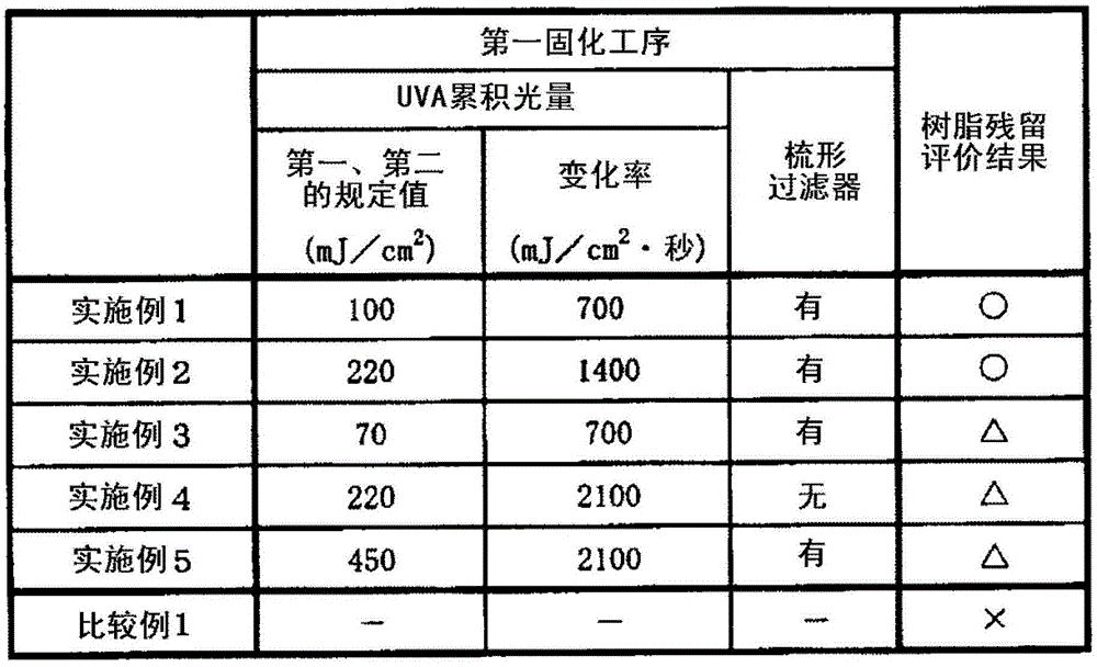
[0108] As shown in Table 1, the first predetermined value and the second predetermined value, and the rate of change of the accumulated light amount per second of UVA of ultraviolet rays were changed, and the same operation as in Example 1 was performed to produce optical film. In addition, in Example 4, no comb filter was used.


PUM

PropertyMeasurementUnit
thicknessaaaaaaaaaa

Abstract

Provided is an optical film manufacturing method which includes: a coating process wherein a coating layer (12) is formed by coating a coating liquid containing an active energy ray-curable resin on a substrate film (11) which is being continuously conveyed; a first curing process wherein active energy rays are irradiated, from the coating layer (12) side, on a fore-region (A) of the coating layer (12); and a second curing process wherein, with the surface of a mold pushed against the surface of the coating layer (12), active energy rays are irradiated on the coating layer (12), from the substrate film (11) side. In the first curing process, it is preferable to also irradiate active energy rays onto a rear region (B) of the coating layer (12). Thus, the present invention provides a method which enables the continual efficient manufacture of an optical film, whilst being able to prevent the generation of resin remains on the mold, and without generating flaws such as defects.

Description

technical field [0001] The present invention relates to a method for producing an optical film in which a coating solution containing an active energy ray-curable resin is coated on a base film and cured. Moreover, this invention relates to the polarizing plate and image display apparatus which used this optical film. Background technique [0002] An optical film in which a resin layer having a predetermined optical function is formed by coating on a base film is used for various image displays such as liquid crystal display devices, such as an anti-glare film, a light diffusion film, and a hard coat film. device. [0003] Generally, the above-mentioned resin layer included in the optical film is formed by applying a coating liquid containing an active energy ray-curable resin on a base film, and irradiating the obtained coating layer with active energy rays to cure it. In order to impart a desired shape to the surface of the resin layer depending on the optical characteri...

Claims


Application Information

Patent Timeline
Patent Type & Authority Patents(China)
IPC IPC(8): B29C39/22B29C39/18B29C59/04B32B7/02B32B27/18G02B1/10G02B5/02G02B5/30B29L7/00B29L11/00G02B1/111G02B1/14G02F1/1335
CPCB29C35/10B29K2995/0034B29C39/18B29C35/0266B29C2035/0827B29C59/046G02B1/10G02B1/11
Inventor 神崎昌
Owner SUMITOMO CHEM CO LTD
Why Eureka
Try Eureka