Arranging device for installing pipetting tips into tip box

A sorting device and gun tip box technology, applied in the direction of packaging, can solve the problems of time-consuming and labor-intensive, and achieve the effect of safe operation, simple structure and high arrangement efficiency

Inactive Publication Date: 2013-09-04
NINGBO UNIV
View PDF9 Cites 18 Cited by
  • Summary
  • Abstract
  • Description
  • Claims
  • Application Information

AI Technical Summary

Problems solved by technology

When an experiment is needed, the experimenter inserts the scattered pipette tips one by one into the round hole of the tip box, which is a time-consuming and troublesome task

Method used


Image

  • Arranging device for installing pipetting tips into tip box
  • Arranging device for installing pipetting tips into tip box
  • Arranging device for installing pipetting tips into tip box

Examples


Embodiment 1

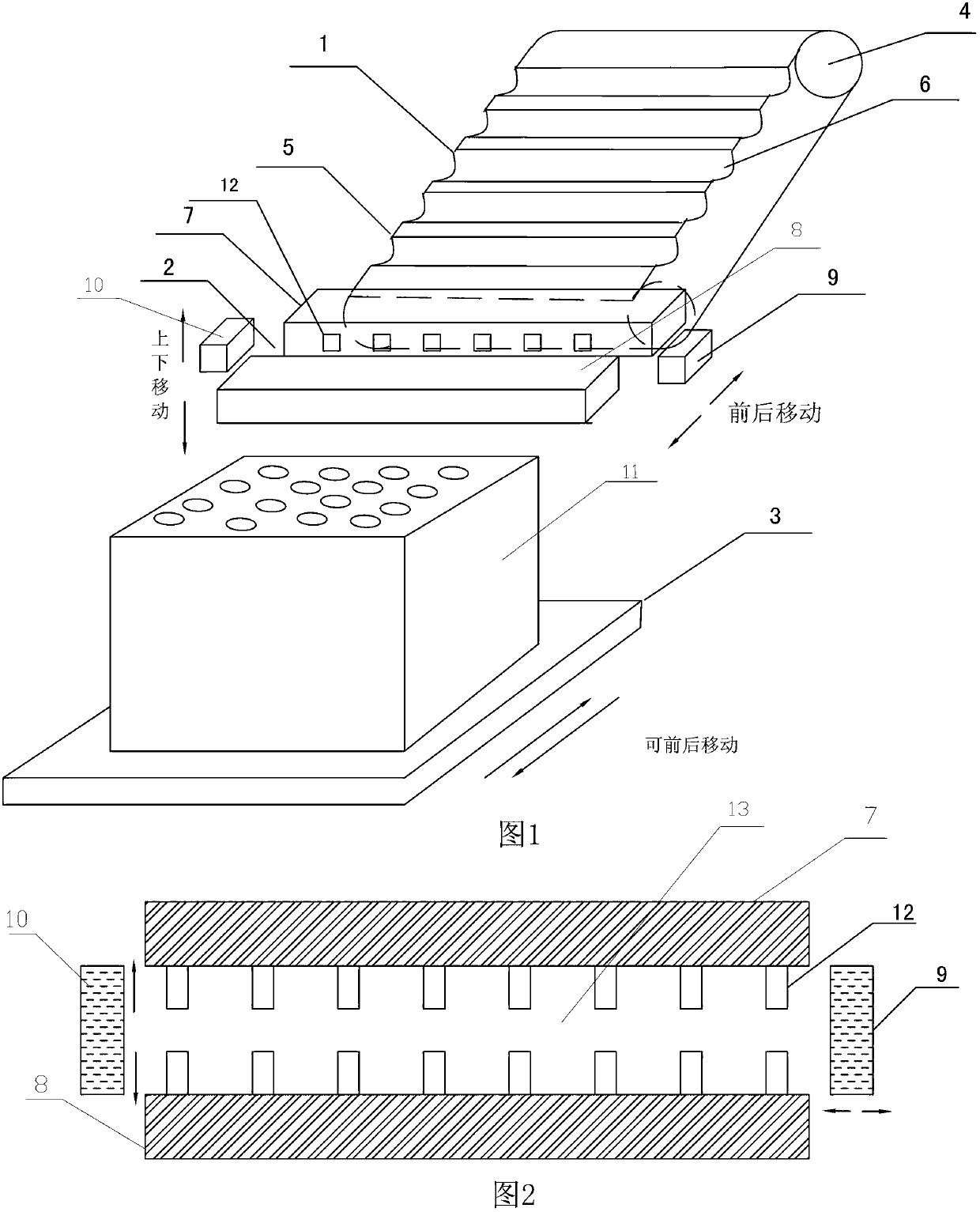
[0022] Embodiment 1: The arrangement device for installing pipette tips into the tip box includes a conveying device 1 , a tip placement device 2 , a vertical lifting mechanism and a storage table 3 for placing the tip box 11 . Transmission device 1 comprises conveyor belt 5 and transmission wheel 4, and transmission belt 5 is driven by transmission wheel 4, and transmission belt 5 is provided with the semicircle groove 6 that can hold the liquid pipette tip, and the extending direction of semicircle groove 6 and clip The extending directions of the grooves 13 are parallel. The gun tip placement device 2 is located above the gun tip box 11 and can move up and down under the action of the vertical lifting mechanism. The gun tip placement device 2 includes a clamping assembly, a splitting mechanism (not shown in the figure) and a push plate assembly , the clamping assembly includes a clamping groove 13 and is controlled by the opening and closing mechanism. The clamping assembl...

Embodiment 2

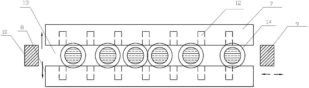
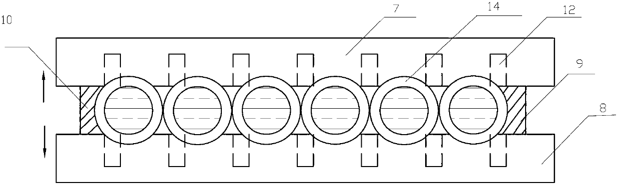
[0023] Embodiment 2: Another sorting scheme implementation of the sorting device in which the pipette tip is installed in the tip box is similar to that of Example 1, the difference is that there are retractable insertion rods 12 evenly spaced on the inner side of the clamping assembly. The pipette tips are closely arranged in front of the clamping groove 13, and the insertion rod 12 is retracted into the clamping assembly. The push plate assembly located at both ends of the clamping groove 13 closely arranges all the pipette tips 15 in the clamping groove 13 . At this time, the distance between the closely arranged pipette tips 15 does not correspond to the round hole spacing on the tip box 11 . After the insertion rod 12 is stretched out, it is located between the tube bodies of the two pipette tips 15, and evenly separates the closely arranged pipette tips 15 in the clamping groove 13. At this time, the pipette tips 15 are aligned with the pipette tips. The hole position of...


PUM


Abstract

The invention discloses an arranging device for installing pipetting tips into a tip box. The arranging device is composed of a driving device, a tip arranging device and an object placing platform. The driving device conveys the pipetting tips to clamping slots of the tip arranging device. A plurality of pipetting tips are vertically erected in the clamping slots, wherein openings of the pipetting tips are arranged upwards. Push plate assemblies which are located at the two ends of the clamping slots tightly rank all the pipetting tips which are located in the clamping slots. The tip arranging device feeds a row of pipetting tips in the clamping slots into a row of hole positions of the tip box, the clamping slots of the push plate assemblies are separated, the pipetting tips drop into the tip box after separating from the clamping slots, the tip arranging device is restored to an original state, the driving device continues to convey the pipetting tips which are scatteredly distributed to the tip arranging device and conducts arrangement of the pipetting tips of a next row of hole positions, and the process is repeated until the pipetting tips are ranked in the whole tip box in order. Staff in a laboratory only needs to place the scattered pipetting tips into the device, and then the device can automatically achieve arranging and inserting of the pipetting tips, so that the arranging device for installing the pipetting tips into the tip box is very convenient to use.

Description

technical field [0001] The invention relates to an instrument used in a biochemical laboratory, in particular to a sorting device in which a pipette tip is installed in a tip box. Background technique [0002] When the experimenter is doing biochemical experiments, put the pipette tip on the mouth of the pipette gun. By operating the pipette gun, a certain amount of liquid can be sucked and then discharged. Many pipette tips are neatly inserted into the tip box. The gun tip box is a plastic frame body, a shelf plate is arranged on the upper end of the gun tip box, and round holes arranged vertically and horizontally are arranged on the shelf plate. The pipette tip is a tubular body, the lower end of the tubular body is tapered, the upper end of the tubular body is open, and a retaining ring is arranged at the upper end of the tubular body, and the lower end of the pipette tip extends into the frame through the round hole on the shelf plate, and the tubular body rest ring on...

Claims


Application Information

Patent Timeline
Patent Type & Authority Applications(China)
IPC IPC(8): B65B35/40
Inventor 沈锡权闫旭红王梦林
Owner NINGBO UNIV
Why Eureka
Try Eureka