
Sorting robot of laser cutting machine and part sorting method of sorting robot

A laser cutting machine and robot technology, applied in sorting, laser welding equipment, manipulators, etc., can solve the problems of inability to achieve safe adsorption, inability to automatically distribute suction cup adsorption, and inability to fully automate, to improve work efficiency and speed. The effect of effective automatic sorting of finished products

Active Publication Date: 2017-08-08
YANGZHOU HENGJIA AUTOMATION EQUIP CO LTD
View PDF6 Cites 16 Cited by
  • Summary
  • Abstract
  • Description
  • Claims
  • Application Information

AI Technical Summary

Problems solved by technology

[0002] Laser cutting machines are widely used in sheet metal processing, metal processing, advertising production, kitchen utensils, automobiles, lamps, saw blades, electrical switch cabinets, metal crafts, textile machinery, grain machinery, glasses production, aerospace, medical equipment, instrumentation, etc. Industry, especially in the sheet metal processing industry, has replaced the traditional processing method, and is favored by industry users; laser cutting machine is a device that uses laser as a processing method to cut and process plates, and it can process curves of any shape; In order to improve the efficiency and automation level of laser cutting and reduce the labor intensity of people, the laser cutting machine sorting robot came into being. It is integrated with the laser cutting machine as a whole and is widely used in various industries; but in daily use, The general laser sorting robot moves through the X-axis, Y-axis, and Z-axis and cannot be fully automated. Even if it can be automated, it cannot identify different finished parts well, nor can it automatically assign the best position for the suction cup to absorb. Less than the effect of safe adsorption

Method used


Image

  • Sorting robot of laser cutting machine and part sorting method of sorting robot
  • Sorting robot of laser cutting machine and part sorting method of sorting robot
  • Sorting robot of laser cutting machine and part sorting method of sorting robot

Examples


Embodiment Construction

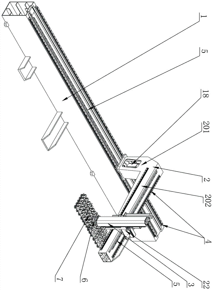
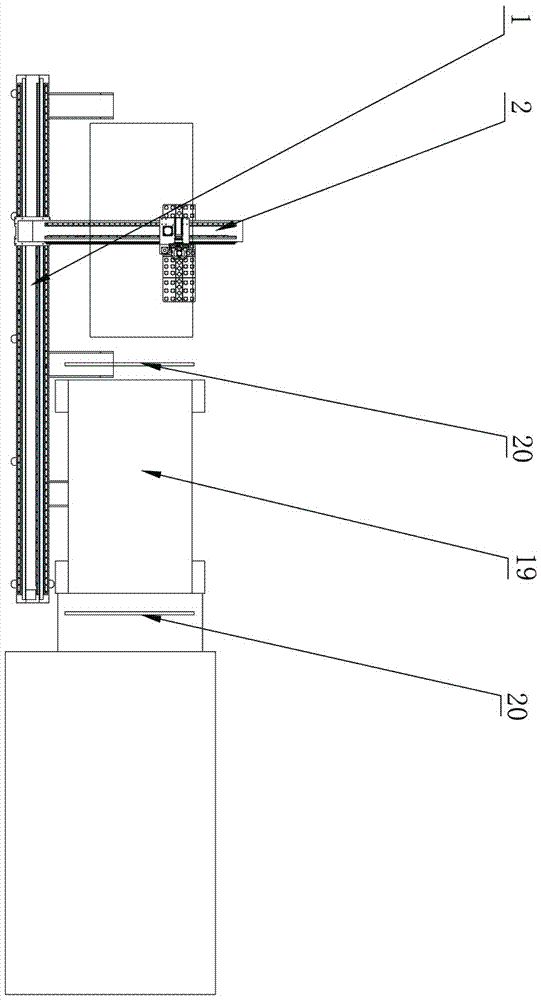
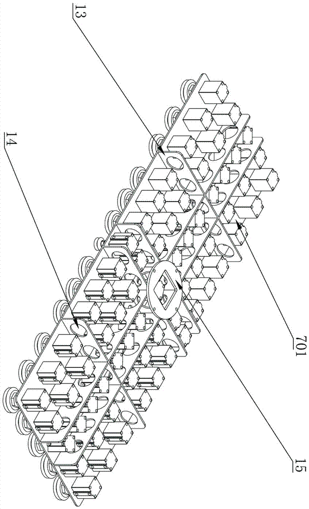
[0031] Such as Figure 1-12As shown, the purpose of the present invention is achieved in this way: a laser cutting machine sorting robot, including an X-axis support seat 1 arranged on the ground, a Y-axis support seat 2 arranged with the X-axis support seat 1, and a Y-axis support seat 2 arranged with the Y-axis support seat. The Z-axis support seat 3 provided on the support seat 2, the X-axis support seat 1, the Y-axis support seat 2 and the Z-axis support seat 3 are respectively provided with a track 4 and a rack 5, and the Y-axis support seat 2 includes a Y-axis longitudinal support seat 201 and the Y-axis transverse support seat 202, the Y-axis longitudinal support seat 201 is set through a sliding mechanism in conjunction with the track 4 on the X-axis support seat 1, and the Z-axis support seat 3 and the Y-axis transverse support seat 202 are connected by a connecting piece 22; Z The shaft supporting seat 3 is equipped with a C-axis supporting seat 6, and the C-axis sup...


PUM


Abstract

The invention discloses a sorting robot of a laser cutting machine and a part sorting method of the sorting robot and belongs to the field of machine tools. A Y-axis support seat comprise a Y-axis longitudinal support seat and a Y-axis transverse support seat; the Y-axis longitudinal support seat is matched with a rail on an X-axis support seat through a sliding mechanism; a Z-axis support seat and the Y-axis transverse support seat are connected through a connecting piece; a C-axis support seat is matched with the Z-axis support seat; the C-axis support seat is driven by a driving device and is connected with a sorting tool; the sorting tool comprises a master panel; a plurality of air cylinders are arranged on the master panel in an array; and each air cylinder is separately connected with a sucking disc. The sorting robot of the laser cutting machine can replace the laser cutting machine for manual sorting, can identify a finished product cut by laser, and rapidly sort and stack the cut finished product.

Description

technical field [0001] The invention relates to a laser cutting machine sorting robot in the field of machine tools and a method for sorting parts by the laser cutting machine sorting robot. Background technique [0002] Laser cutting machines are widely used in sheet metal processing, metal processing, advertising production, kitchen utensils, automobiles, lamps, saw blades, electrical switch cabinets, metal crafts, textile machinery, grain machinery, glasses production, aerospace, medical equipment, instrumentation, etc. Industry, especially in the sheet metal processing industry, has replaced the traditional processing method, and is favored by industry users; laser cutting machine is a device that uses laser as a processing method to cut and process plates, and it can process curves of any shape; In order to improve the efficiency and automation level of laser cutting and reduce the labor intensity of people, the laser cutting machine sorting robot came into being. It is...

Claims


Application Information

Patent Timeline
IPC IPC(8): B23K26/70B25J11/00B25J9/16B07C5/00
CPCB07C5/00B23K26/702B25J9/1679B25J11/00
Inventor 王涛卞隆元蔡思琪
Owner YANGZHOU HENGJIA AUTOMATION EQUIP CO LTD
Learn More