Corridor transportation device

A technology for transportation devices and corridors, applied in the field of transportation devices in corridors, can solve the problems of increased construction costs, construction interference along the line, high labor intensity, etc., and achieve the effects of avoiding slippage, fast transportation speed, and low labor intensity

Active Publication Date: 2015-12-09
CHINA GEZHOUBA GROUP CO LTD
View PDF8 Cites 0 Cited by
  • Summary
  • Abstract
  • Description
  • Claims
  • Application Information

AI Technical Summary

Problems solved by technology

Due to the narrow space in the corridor, when there are many construction equipment in the transfer line, such as grouting construction in tunnels or corridors, the arrangement of construction machinery and equipment such as drilling rigs and grouting machines is relatively dense, so manual transportation is affected by the construction equipment along the way, which is very difficult , the transportation speed is slow, the labor intensity is high, and there is a large interference to the construction along the line
[0003] The method of manually transporting the spoil in the corridor is commonly used in engineering. Generally speaking, if no measures are taken, the spoil in the corridor needs to be manually transported from the corridor to the outside. This transportation method not only consumes man-hours, but also increases Construction cost, and not safe, especially for sloping corridors, very labor intensive

Method used


Image

  • Corridor transportation device
  • Corridor transportation device
  • Corridor transportation device

Examples


Embodiment 1

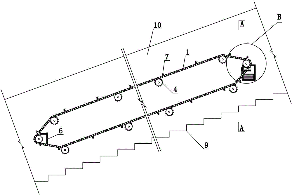
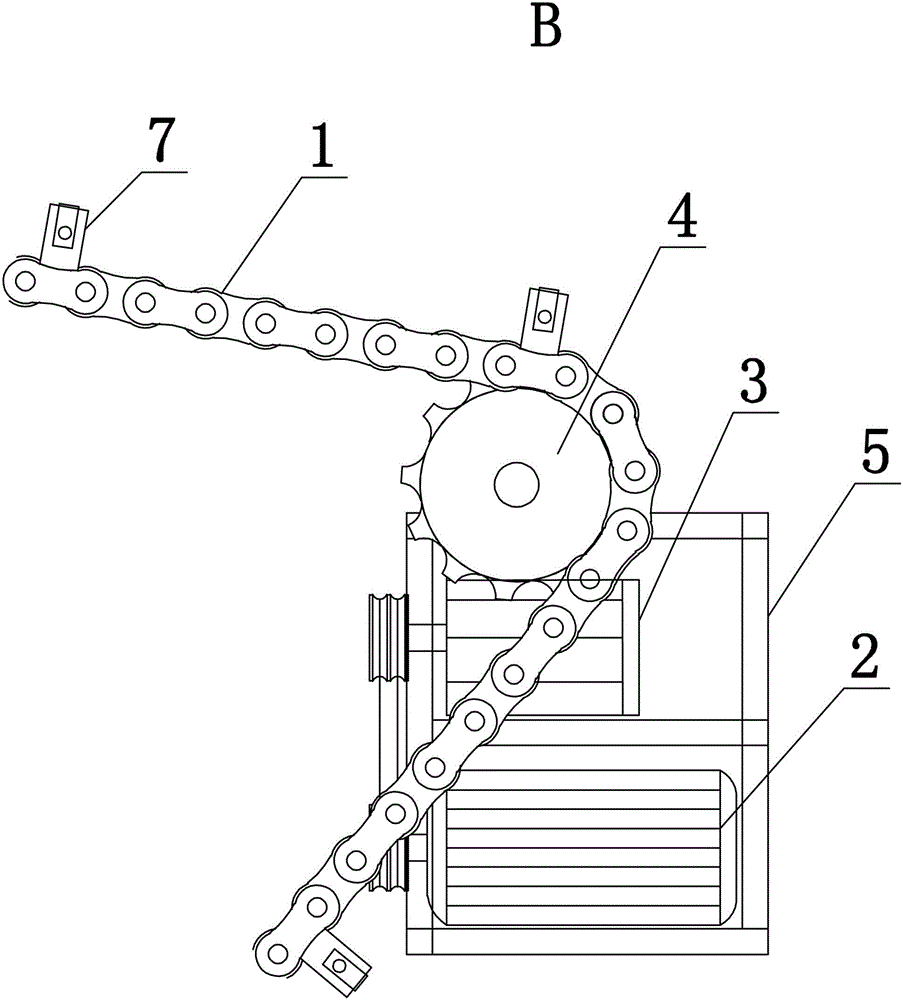
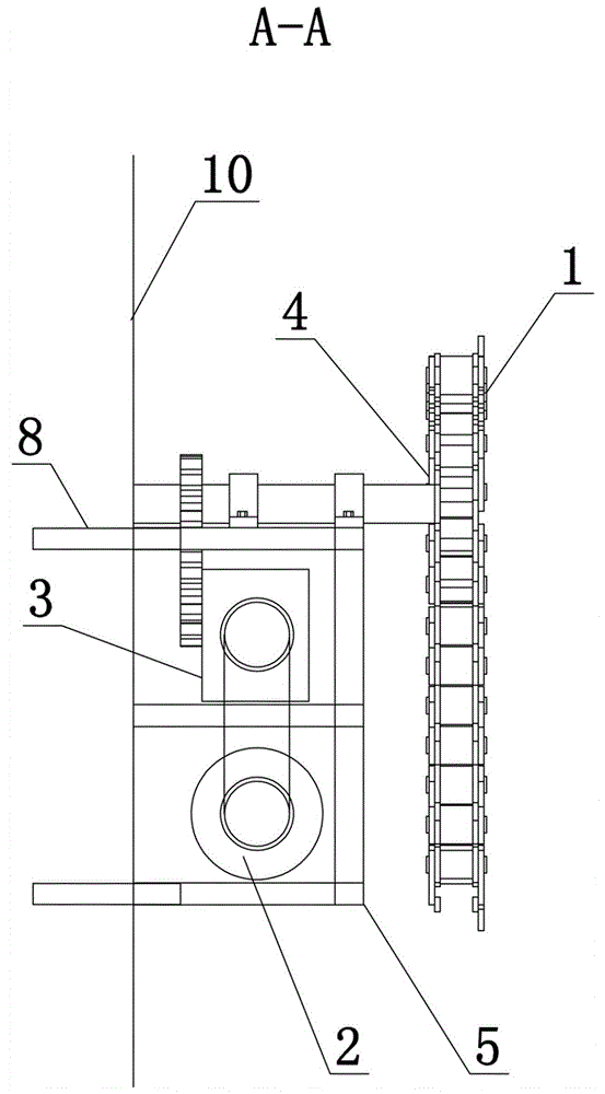
[0025] Such as Figure 1-3 Among them, a transportation device in a corridor, a plurality of sprockets 4 are arranged on the side wall 10 of the corridor through a driven wheel bracket 6, and at least one driving wheel frame 5 is arranged, and the driving wheel frame 5 is fixed on the side of the corridor through an anchor rod 8 On the wall 10, the driving sprocket on the driving wheel frame 5 is connected with the driving device, and the chain 1 connects the driving sprocket and each sprocket 4, and forms a chain conveying device circulating along a section of corridor 9. There are multiple suspension hooks 7 . The drive in this example is figure 2 As shown in , the motor 2 installed on the drive wheel frame 5 is connected to the gearbox 3, and the gearbox 3 is connected to the drive sprocket, the rotation of the motor drives the drive sprocket to rotate, and the chain 1 is driven to rotate accordingly, and each driven The sprocket 4 rotates thereupon, and the waste slag o...

Embodiment 2

[0027] An optimized solution such as Figure 4-6 Among them, on the basis of Embodiment 1, a track 11 is also provided on the top of the corridor. In a preferred solution, the track 11 is arranged on the side of the corridor top close to the chain 1 . Track 11 below is provided with the slide device with roller 14, is provided with chain block 17 on the slide device, and traction rope 16 one ends are connected with slide device, and the other end is connected with suspension hook 7 on the chain 1. A hanging basket 18 is also provided below the chain block 17 .

[0028] An optimized solution such as Image 6 Among them, the track 11 is two channel steels with grooves opposite to each other. The back of the channel steel is welded and connected with the anchor bar 12 fixed on the top of the corridor, and the connecting plate 13 is welded at the joint of the track to enhance its overall strength. The sliding device The two ends of the shaft are provided with rollers 14, and the...

Embodiment 3

[0030] For inclined corridors, it is dangerous to only adopt the scheme of embodiment 2, for example, when the traction rope 16 may break, it will cause the weight in the hanging basket 18 to slide backwards and cause an accident. On the basis of Example 2, the further optimized scheme is as Figure 4-8 Among them, a one-way braking device 19 is also provided in the sliding device.

[0031] Such as Figure 5 , 7 , 8, in the one-way braking device 19, one end of the upper wedge 191 and the lower wedge 192 is located in the groove of the track 11, and a spring 193 is arranged between the upper wedge 191 and the lower wedge 192 The other end of upper wedge 191 and lower wedge 192 is movably connected with the shaft, the traction rope 16 is connected with upper wedge 191 and lower wedge 192 respectively, and the other end of traction rope 16 passes guide hole 194 and traction hole 15. Usually, the one-way braking device 19 is arranged in the groove of each rail 11 to ensure tha...


PUM


Abstract

The invention discloses a transportation device used in a corridor. According to the transportation device used in the corridor, a plurality of chain wheels are arranged on the lateral wall of the corridor through a driven wheel support, at least one driving wheel machine frame is arranged, the driving chain wheels on the driving wheel machine frame are connected with a driving device, the driving chain wheels and the chain wheels are connected through chains to form a chain transportation device which circulates along a section of the corridor, and a plurality of hanging hooks are arranged on the chains. According to an optimized scheme, a track is further arranged on the top of the corridor, a sliding device with idler wheels is arranged below the track, a chain block is arranged on the sliding device, one end of a traction rope is connected with the sliding device, and the other end of the traction rope is connected with the hanging hooks. The transportation device used in the corridor has the advantages that due to the arrangement of the chain transportation device, waste slag and articles with weights below 100 kg in the corridor can be transported, and labor intensity is relieved; furthermore, an article with a weight below 400 kg can be transported due to the matching between the track arranged on the top of the corridor and the chain transportation device, the labor intensity is further relieved, interference on ground construction is avoided, and the construction progress is accelerated.

Description

technical field [0001] The invention relates to a transportation device, in particular to a transportation device in a corridor. The transportation device can also be used to transport objects in other places, such as long and narrow corridors and passages inside buildings. Background technique [0002] In the construction of underground projects, it is often necessary to transfer materials, tools and small equipment and other objects in the corridor. The usual way is to manually transfer them from the corridor floor. Due to the narrow space in the corridor, when there are many construction equipment in the transfer line, such as grouting construction in tunnels or corridors, the arrangement of construction machinery and equipment such as drilling rigs and grouting machines is relatively dense, so manual transportation is affected by the construction equipment along the way, which is very difficult , the transportation speed is slow, the labor intensity is high, and there is...

Claims


Application Information

Patent Timeline
Patent Type & Authority Patents(China)
IPC IPC(8): B65G17/12B65G17/30
Inventor 黄家权张新宇林伟杨富瀛李晓萍程雷梓
Owner CHINA GEZHOUBA GROUP CO LTD
Why Eureka
Try Eureka