Pipe flow direct-drive power generating device

A power generation device, direct-drive technology, applied in electromechanical devices, wind power generation, engines, etc., can solve the problems of affecting power utilization, not considering wind energy, wind energy loss, etc., to achieve stable output frequency, avoid energy loss, The effect of improving efficiency

Active Publication Date: 2013-09-04
无锡金蝎中蕴风电科技有限公司
View PDF7 Cites 4 Cited by
  • Summary
  • Abstract
  • Description
  • Claims
  • Application Information

AI Technical Summary

Problems solved by technology

[0002] Wind power generation needs to convert wind energy into electrical energy. If traditional motors are used to generate electricity, there must be a speed-up process in the conversion link from wind energy to electrical energy and the wind energy needs to be converted into a form that can drive a rotating motor. The intermediate power device that drives the motor is usually driven by the intermediate power device to drive the transmission shaft connected to the rotary motor, and then the drive shaft transmits the power to the rotary motor, thereby driving the rotary motor. This type of power generation device The disadvantage is that the shaft transmission process will consume a certain amount of energy, resulting in the energy loss of wind energy, which will eventually affect the utilization rate of power.
In the prior art, there are also direct-drive power generation devices that do not use traditional motors, such as the "low-speed direct-drive wave generator" disclosed in Chinese patent ZL201120327227.9. The rotor core moves relative to the stator coil. Although it can generate electric energy, it does not consider how to use wind energy as much as possible to improve the utilization rate of wind energy and how to generate electric energy more efficiently. In addition, the rotor core in this device is press-fitted in the power generation On the machine shaft, so when high output power is required, the device needs to make the generator shaft into a large diameter or high strength shaft

Method used


Image

  • Pipe flow direct-drive power generating device
  • Pipe flow direct-drive power generating device

Examples


Embodiment Construction

[0018] The specific implementation manner of the present invention will be described below in conjunction with the accompanying drawings.

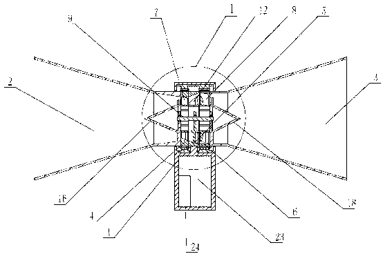
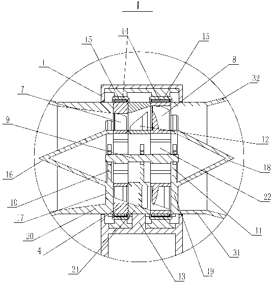
[0019] See figure 1 , figure 2 , the present invention includes a generator housing 1, the two ends of the generator housing 1 are fixedly connected with a shrink tube 2 and a wake tube 3 respectively, the shrink tube 2 and the wake tube 3 communicate in space, and the space between the shrink tube 2 and the wake tube 3 There are at least two stages of rotatable blades, between the shrink tube 2 and the wake tube 3 there are successively a rotor mounting ring 1 4, a guide vane mounting base 5 and a rotor mounting ring 2 6, and the inner wall of the rotor mounting ring 1 4 is fixed with a second The first-stage rotating blade 7, the inner wall of the rotor mounting ring 2 6 is fixedly connected with the second-stage rotating blade 8, the first-stage rotating blade 7 and the second-stage rotating blade 8 are fixedly supported on the suppor...


PUM


Abstract

A pipe flow direct-drive power generating device comprises a generator shell. The two ends of the generator shell are respectively and fixedly connected with a shrinkable pipe and a wake flow pipe. At least two stages of rotatable blades are arranged in the generator shell, the shrinkable pipe and the wake flow pipe are communicated in space, and a first rotor installation ring, a guide blade installation seat and a second rotor installation ring are sequentially arranged between the shrinkable pipe and the wake flow pipe. The inner wall of the first rotor installation ring is fixedly connected with a first-stage rotating blade, the inner wall of the second rotor installation ring is fixedly connected with a second-stage rotating blade, the first-stage rotating blade and the second-stage rotating blade are fixed on a supporting shaft, the two ends of the supporting shaft can be rotationally supported on the inner wall of the communicated space, the inner wall of the guide blade installation seat is fixedly connected with guide blades, the guide blade installation seat is fixed on the generator shell, permanent magnets are arranged on both the periphery of the first rotor installation ring and the periphery of the second rotor installation ring, a stator coil is arranged in the generator shell, the stator coil and the permanent magnets are opposite, and gaps are left among the stator coil and the permanent magnets. According to the pipe flow direct-drive power generating device, a power transmission link of a transmission shaft is eliminated, energy loss in a shaft transmission link is avoided, and the utilization rate of power is improved.

Description

technical field [0001] The invention relates to the technical field of power generation equipment, in particular to a tube-flow direct-drive power generation device capable of omitting a transmission shaft. Background technique [0002] Wind power generation needs to convert wind energy into electrical energy. If traditional motors are used to generate electricity, there must be a speed-up process in the conversion link from wind energy to electrical energy and the wind energy needs to be converted into a form that can drive a rotating motor. The intermediate power device that drives the motor is usually driven by the intermediate power device to drive the transmission shaft connected to the rotary motor, and then the drive shaft transmits the power to the rotary motor, thereby driving the rotary motor. This type of power generation device The disadvantage is that: the shaft transmission process will consume a certain amount of energy, resulting in the energy loss of wind en...

Claims


Application Information

Patent Timeline
Patent Type & Authority Applications(China)
IPC IPC(8): F03D9/00H02K7/18
CPCY02E10/72
Inventor 张红旭杨伟涛谢玉琪姚伯龙李勇良
Owner 无锡金蝎中蕴风电科技有限公司
Why Eureka
Try Eureka