Wind control and diversion device for air cooling island of power station

A technology of diversion devices and air-cooling islands, which is applied in steam/steam condensers, lighting and heating equipment, etc. It can solve the problems that the environmental wind field has adverse effects on air-cooling islands and cannot effectively improve the heat transfer efficiency of the air-cooling island heat exchange environment. , achieve good promotion and application prospects, improve economy and safety, and have remarkable application effects

Active Publication Date: 2016-02-03
GUODIAN LONGYUAN POWER TECH ENG
View PDF6 Cites 0 Cited by
  • Summary
  • Abstract
  • Description
  • Claims
  • Application Information

AI Technical Summary

Problems solved by technology

[0004] The technical problem to be solved by the present invention is: in order to solve the problem that the "wind-shielding" technology adopted by the air-cooling island of the current air-cooling unit is not enough to overcome the adverse effects of the ambient wind field on the heat exchange of the air-cooling island, and cannot effectively improve the exchange rate of the air-cooling island. To solve the problem of thermal environment and help improve heat exchange efficiency, a wind control and diversion device for the air cooling island of the power station is disclosed. The ambient wind is effectively controlled and guided, so that the ambient wind entering the air-cooled island is most conducive to the heat dissipation of the air-cooled island (at least the ambient wind will not affect the heat dissipation of the air-cooled island)

Method used


Image

  • Wind control and diversion device for air cooling island of power station
  • Wind control and diversion device for air cooling island of power station
  • Wind control and diversion device for air cooling island of power station

Examples


Embodiment Construction

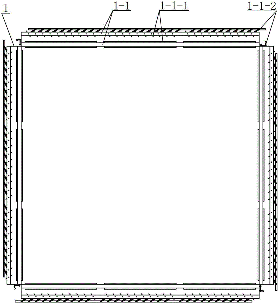
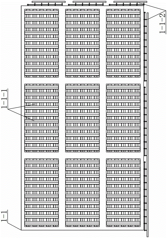
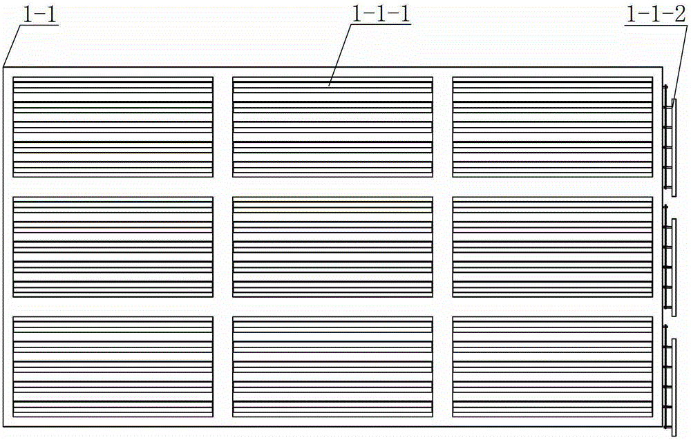
[0020] A wind control and diversion device for the air-cooled island of a power station, such as Figure 1 to Figure 4 As shown, it includes several road control wind guide walls 1 arranged around the air cooling island ( figure 1 There are 4 channels in the middle, and these 4 air-controlling and diversion walls are arranged in a rectangular shape around the air-cooling island, basically forming a circle around the air-cooling island. around the air-cooled island to form a circle of diversion walls), each air-control diversion wall 1 is composed of inner and outer two-layer opening-adjustable louver-type air deflectors 1-1, and the inner and outer two-layer openings The axial directions of the rotating shafts of the louvers 1-1-1 of the adjustable louver type wind deflector 1-1 are perpendicular to each other.

[0021] The opening of each louver 1-1-1 of the louver-type wind deflector 1-1 with adjustable opening is controlled by a driving motor through its own rotating shaft...


PUM


Abstract

The invention relates to an air controlling and flow guiding device for an air cooling island of a power station. The air controlling and flow guiding device comprises a plurality of air controlling and flow guiding walls which are distributed around the air cooling island, each air controlling and flow guiding wall comprises an inner openness-adjustable louver type air guiding plate and an outer openness-adjustable louver type air guiding plate, and louver rotating shafts of each inner openness-adjustable louver type air guiding plate and each outer openness-adjustable louver type air guiding plate are axially vertical to each other. By the air controlling and flow guiding device, environmental wind entering the air cooling island of the power station can be effectively controlled and guided under different environmental wind field conditions, the environmental wind entering the air cooling island is enabled to be the most beneficial to the radiation of the air cooling island, and the air controlling and flow guiding device is quite remarkable in application effect and plays a remarkable key role in improving economical efficiency and safety of an air cooling unit. In addition, the air controlling and flow guiding device is simple in structure and low in manufacturing cost, and has excellent popularization and application prospects in large-capacity air cooling units put into operation currently.

Description

technical field [0001] The invention relates to an air regulating and diverting device, in particular to an air controlling and diverting device for the air cooling island of a power station, which is used to adjust the speed and direction of the ambient wind entering the air cooling island, so as to reduce the impact of the ambient wind on the air cooling. The influence of the cooling effect of the island and the purpose of assisting in improving the cooling effect of the air-cooled island. Background technique [0002] With the rapid development of the power industry, newly installed thermal power generating units have gradually developed to focus on large-capacity, supercritical, and ultra-supercritical units, and the water-scarce areas (three north regions) focus on developing large-capacity direct air-cooled units. For a large number of direct air-cooling units put into operation intensively, it is imminent to improve their operating economy and safety. The air-cooled ...

Claims


Application Information

Patent Timeline
Patent Type & Authority Patents(China)
IPC IPC(8): F28B9/00
Inventor 姜媛媛赵虎军腾东玉王文波王公林
Owner GUODIAN LONGYUAN POWER TECH ENG
Why Eureka
Try Eureka