Pressed-type switch with kick function

A sudden jump and functional technology, applied in the direction of electric switches, electrical components, circuits, etc., can solve the problems of complex structure, poor operation flexibility, and short service life of push switches, so as to ensure stability, force balance, and avoid wear and tear Effect

Active Publication Date: 2013-09-04
KEDU ELECTRIC CO LTD
View PDF5 Cites 5 Cited by
  • Summary
  • Abstract
  • Description
  • Claims
  • Application Information

AI Technical Summary

Problems solved by technology

[0004] For this reason, the first technical problem to be solved by the present invention is that the existing push switch with a jump function has a complex structure, low assembly efficiency and short service life;
[0005] The second technical problem to be solved by the present invention is that the existing push switch with a jump function has poor operational flexibility.

Method used


Image

  • Pressed-type switch with kick function
  • Pressed-type switch with kick function
  • Pressed-type switch with kick function

Examples


Embodiment Construction

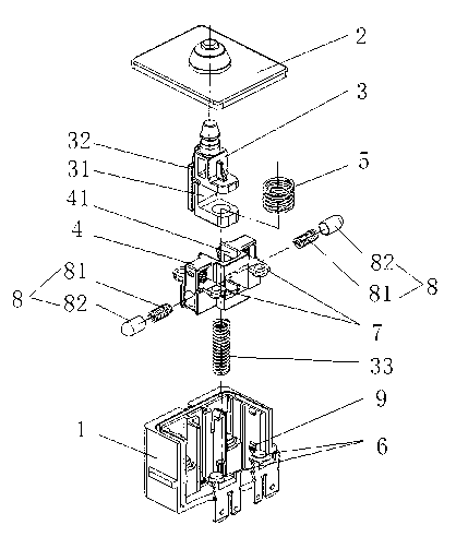
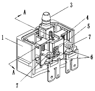
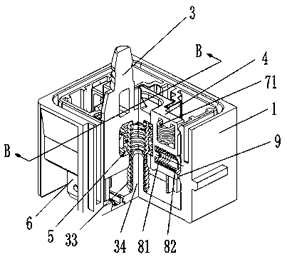
[0029] see Figure 1-4 , a push switch with kick function of the present invention, comprising a housing 1, a button assembly slidably installed inside the housing 1, an end cover 2 is provided at the end of the button assembly, and a The contact assembly in the housing 1, the contact assembly includes a moving contact part driven by the button assembly and a static contact part fixed relative to the housing 1, and the static contact part includes A static contact 6 with two static contacts is formed on the housing, and the moving contact part includes a moving contact 7 and a moving contact frame 4 for supporting the moving contact; Sliding down or upward drives the moving contact part to contact or separate from the static contact 6, and a jumping structure is set between the moving contact frame 4 and the housing 1, and the jumping structure includes a The bump 9 on the housing 1, and the jump assembly arranged on the moving contact frame 4 and matched with the bump 9, the...


PUM


Abstract

The invention relates to a pressed-type switch with a kick function. The pressed-type switch with the kick function comprises a shell, a button assembly and a contact assembly, wherein the button assembly is arranged in the shell in a sliding mode. The contact assembly comprises a moving contact component and a fixed contact component, wherein the moving contact component is driven by the button assembly, and the fixed contact component is fixed relative to the shell. The moving contact component comprises a moving contact and a moving contact support used for supporting the moving contact. The button assembly slides to drive the moving contact component to be contacted with or separated from the fixed contact component. A kick structure is arranged between the moving contact support and the shell. The kick structure comprises a lug and a kick assembly, wherein the lug is arranged on the shell, and the kick assembly is arranged on the moving contact support and matched with the lug. The kick assembly is made to slip along an inclined plane of the lug when the button assembly slides. The pressed-type switch with the kick function is flexible in operation, fast to assemble and low in process cost, and fast testing and slow testing can be carried out through the switch.

Description

technical field [0001] The invention relates to the field of electric switches, in particular to a push switch with a kick function. Background technique [0002] In order to facilitate the control and operation of electric tools such as electric drills, electric hammers, and electric grinders, the control switches of such products are generally set at the position of the index finger on the handle. The traditional push switch mainly drives the contact frame to move downward by pressing the button, so that the movable contact arranged on the movable contact holder and the static contact arranged on the base contact and conduct current, and then drive the electric tool to work. Due to the severe vibration of most electric tools during use, the index finger or other fingers that control the switch will not always be pressed against the button of the switch due to vibration, resulting in contact between the moving contact and the static contact. Unstable, and even damage elect...

Claims


Application Information

Patent Timeline
Patent Type & Authority Applications(China)
IPC IPC(8): H01H13/52H01H13/28H01H13/04H01H13/12
Inventor 郑春开李子平田昊
Owner KEDU ELECTRIC CO LTD
Why Eureka
Try Eureka