Power grid power failure or artificial switch power failure intelligent identification power supply
An intelligent identification and man-made technology, applied in the field of power electronics, can solve the problems that power failure emergency products cannot be controlled by wall switches, and ordinary lighting products cannot distinguish power failures or artificial power failures.
- Summary
- Abstract
- Description
- Claims
- Application Information
AI Technical Summary
Problems solved by technology
Method used
Image
Examples
Embodiment 1
[0035] Embodiment 1: The intelligent identification power supply is used for the control of civilian light-emitting diode lighting fixtures with backup power supply after power failure.
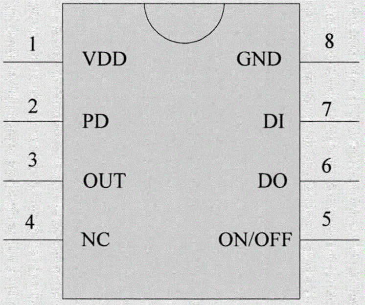
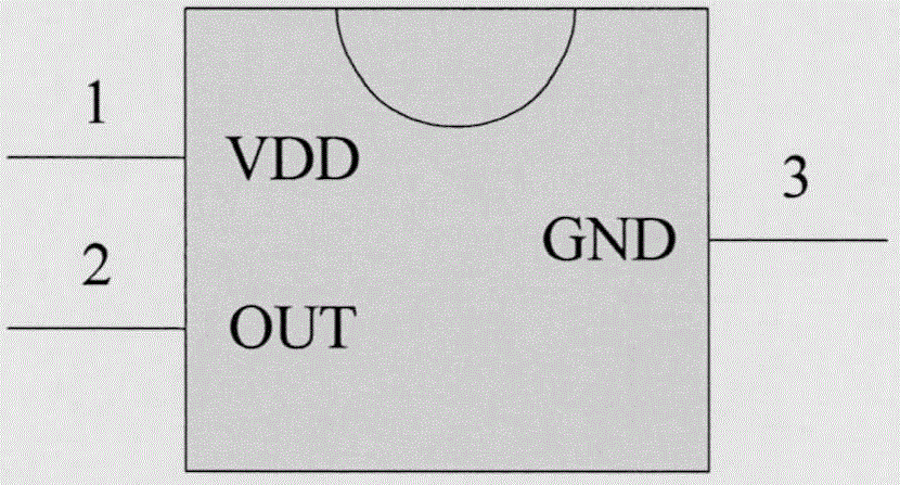
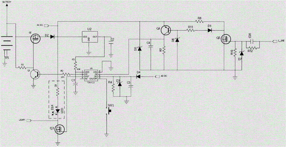
[0036] The present invention is an intelligent identification power supply for grid power failure or artificial switch power failure, which includes a low-power single-chip microcomputer, a positive voltage reference voltage source chip, and peripheral auxiliary circuits; figure 1 Shown is the pin diagram of the low-power MCU, figure 2 It is the pin diagram of the positive voltage reference voltage source chip, and the circuit schematic diagram when it is used in Embodiment 1 is as follows image 3 shown. image 3 The AC-DC terminal in the middle indicates the power supply terminal when the connected lamp is working normally; the L_LINE terminal is the connection terminal between the device and the live wire; the BATTERY terminal is the connection terminal between the device and the built-i...
Embodiment 2
[0043] Embodiment 2: The intelligent recognition power supply for grid power outage or artificial switch power outage is used for line transformation of ordinary light-emitting diode lamps to upgrade to intelligent lamps with emergency lighting function.
[0044] The present invention is an intelligent identification power supply for grid power failure or artificial switch power failure, which includes a low-power single-chip microcomputer, a positive voltage reference voltage source chip, and peripheral auxiliary circuits; figure 1 Shown is the pin diagram of the low-power MCU, figure 2 It is the pin diagram of the positive voltage reference voltage source chip, and the circuit schematic diagram when it is used in Embodiment 2 is as follows Figure 5 shown.
[0045] Figure 5 The AC-DC terminal in the middle indicates the power supply terminal for the module when the connected electrical appliances work normally; the L_LINE terminal is the connection terminal between the e...
PUM
 Abstract
Description
Claims
Application Information
 - R&D
- Intellectual Property
- Life Sciences
- Materials
- Tech Scout
- Unparalleled Data Quality
- Higher Quality Content
- 60% Fewer Hallucinations
Browse by: Latest US Patents, China's latest patents, Technical Efficacy Thesaurus, Application Domain, Technology Topic, Popular Technical Reports.
© 2025 PatSnap. All rights reserved.Legal|Privacy policy|Modern Slavery Act Transparency Statement|Sitemap|About US| Contact US: help@patsnap.com


