

Catalyst tremie pipe
A catalyst and feeding tube technology, applied in the field of reactors, can solve the problems of the fan-shaped cylinder or the central tube being squeezed and deformed by the catalyst, the flow pattern of the catalyst particles deviates from the plug flow, and the effective volume utilization rate of the reactor is low. Practical value and economic significance, improving the effective volume utilization rate, and the effect of low manufacturing and installation difficulty
- Summary
- Abstract
- Description
- Claims
- Application Information
AI Technical Summary
Problems solved by technology
Method used
Image

Examples
Embodiment 1
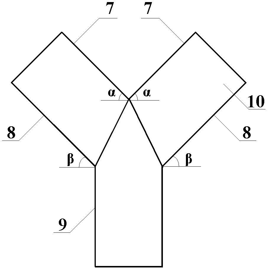
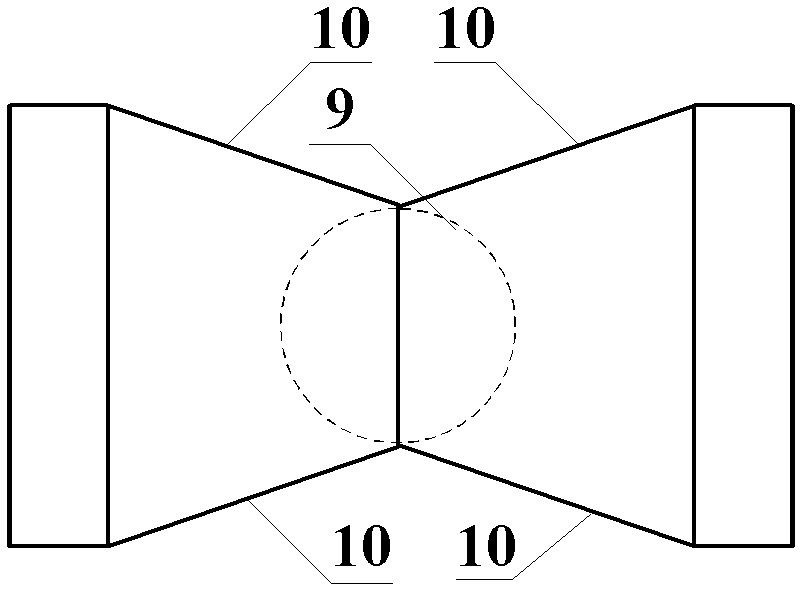
[0031] like figure 1 and figure 2 As shown, the catalyst feeding pipe of the present invention includes a guide tube 9 and two symmetrically arranged side ports that communicate with the same tube opening of the guide tube 9 . The two ends of the guide tube 9 are not closed.
[0032] The cross section of the guide tube 9 is circular. The catalyst feeding pipe is symmetrical along the central axis of the draft tube 9 .
[0033] The port area of the side interface gradually increases from the connection with the guide tube 9. Specifically, it can be set as follows: the side interface includes an isosceles trapezoidal top plate 7, an isosceles trapezoidal bottom plate 8, and a connection between the top plate 7 and the bottom plate 8. Two right-angled trapezoidal side plates 10; the upper base of the top plate 7, the upper base of the bottom plate 8, and the inclined waists of the two side plates 10 are connected with the mouth of the guide tube 9; the lower base of the to...
Embodiment 2
[0039] like Image 6 As shown, the present invention adopts the continuous catalytic reforming radial reactor of the Y-type catalyst feeding pipe in Embodiment 1, and the reactor is composed of an upper head 11, a cylindrical reactor body 12 and a bottom head 13. the outer shell of the device. A gas inlet pipe 14 and a gas outlet pipe 15 are provided on the outer casing of the reactor, wherein the gas inlet pipe 14 is arranged on the upper head 11 . A central pipe 16 coaxial with the reactor cylinder 12 is arranged on the central axis of the reactor cylinder 12 , and the gas outlet pipe 15 communicates with the central pipe 16 . The inner wall of the reactor cylinder 12 is evenly provided with a plurality of fan-shaped cylinders 17, and along the inner circumference of the annulus between the fan-shaped cylinders 17 and the central pipe 16, 8 Y tubes in Example 1 uniformly distributed along the circumference of the central pipe 16 are evenly arranged. Type catalyst feed pipe...
Embodiment 3
[0047] The present invention adopts the moving bed methanol-to-olefins radial reactor of the Y-type catalyst feeding pipe in Example 1, except that the continuous catalytic reforming radial reactor adopted in Example 2 is replaced by a moving bed methanol-to-olefins radial reactor. Reactor, other structures are all the same as embodiment 2.
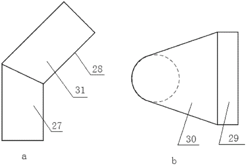
[0048] The structure of the above-mentioned moving bed methanol-to-olefins radial reactor and its components, except that the catalyst feed pipe 26 adopts the Y-shaped catalyst feed pipe in Embodiment 1, the rest of the components are conventional parts, and the catalyst feed pipe 26 The arrangement, the operation process of the reactor and the operating conditions are also conventional methods or conditions, so only the above brief description is given.
[0049] The catalyst feeding pipe 26 used in Example 1, wherein, the number of catalyst feeding pipes 26 is 20, and the plate thickness is 0.5mm. The ratio of the length of the rectangu...
PUM
 Abstract
Description
Claims
Application Information