Catalyst tremie pipe

A catalyst and feeding tube technology, applied in the field of reactors, can solve the problems of fan-shaped tube or central tube being squeezed and deformed by the catalyst, the flow pattern of catalyst particles deviating from plug flow, and the low utilization rate of the effective volume of the reactor. Small catalyst flow dead zone, large practical value and economic significance, and the effect of improving effective volume utilization

Inactive Publication Date: 2013-09-11
ZHEJIANG UNIV
View PDF7 Cites 2 Cited by
  • Summary
  • Abstract
  • Description
  • Claims
  • Application Information

AI Technical Summary

Problems solved by technology

[0007] The technical problems to be solved by the present invention are: the dead zone of the solid catalyst particles in the reactor caused by the use of the existing catalyst feeding pipe is large, the effective volume utilization rate of the reactor is low, the flow pattern of the catalyst particles seriously deviates from the plug flow and During the operation of the device, the catalyst in the dead zone will cause runaway temperature due to severe coking, and even cause the fan-shaped tube or central tube in the reactor to be squeezed and deformed by the catalyst

Method used


Image

  • Catalyst tremie pipe
  • Catalyst tremie pipe
  • Catalyst tremie pipe

Examples


Embodiment 1

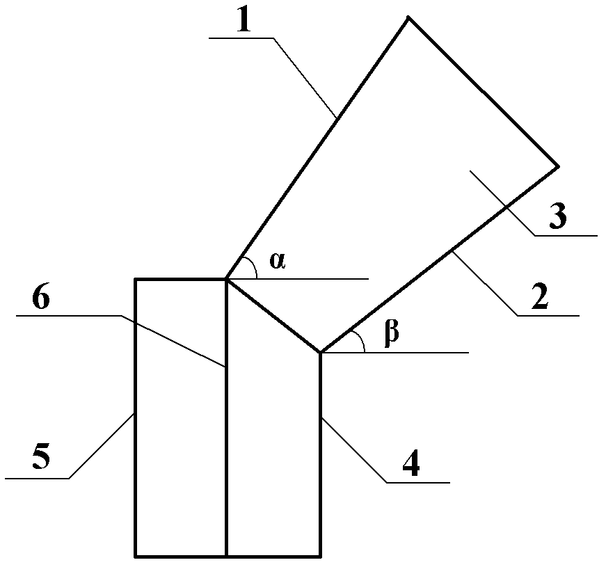
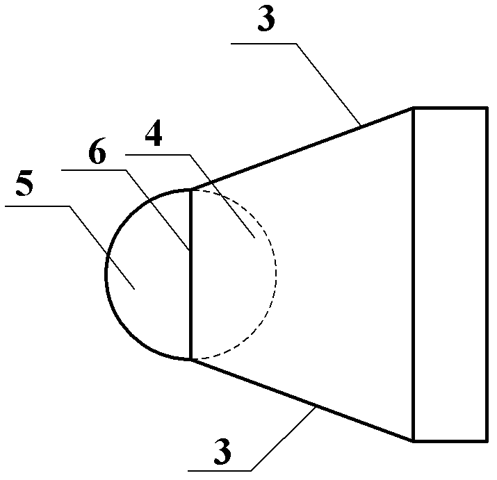
[0034] Such as figure 1 and figure 2 As shown, the catalyst feeding pipe of the present invention includes a guide tube and a side port, and a partition 6 is arranged in the guide tube, and the partition 6 is perpendicular to the cross section of the guide tube and divides the guide tube into side ports to guide The flow tube 4 and the center interface guide tube 5; the side interface guide tube 4 communicates with the side interface. Both ends of the side interface guide tube 4 and the center interface guide tube 5 are not closed. The cross section of the guide tube is circular, and the cross sections of the side interface guide tube 4 and the central interface guide tube 5 are both semicircular. The catalyst feeding pipe is symmetrical along a plane perpendicular to the partition 6 and passing through the central axis of the partition 6 . A port of the side interface away from the side interface guide tube 4 is higher than the mouth of the central interface guide tube 5...

Embodiment 2

[0041] Such as Figure 6 As shown, the present invention adopts the moving bed methanol-to-olefins radial reactor of the r-type catalyst feeding pipe in Example 1, and the reactor is composed of an upper head 11, a cylindrical reactor shell 12 and a bottom head 13. Reactor outer shell. A gas inlet pipe 14 and a gas outlet pipe 15 are provided on the outer casing of the reactor, wherein the gas inlet pipe 14 is arranged on the upper head 11 . A central pipe 16 coaxial with the reactor cylinder 12 is arranged on the central axis of the reactor cylinder 12 , and the gas outlet pipe 15 communicates with the central pipe 16 . A plurality of fan-shaped tubes 17 are uniformly arranged on the inner wall of the reactor cylinder 12, and 20 r Type catalyst feed pipe 25 (such as figure 1 and figure 2 shown). The annular space 18 between the central pipe 16 and the fan-shaped cylinder 17 is filled with catalyst, which is a catalyst flow channel. When the gas flow form is centripeta...

Embodiment 3

[0049] The present invention adopts the continuous catalytic reforming radial reactor of the r-type catalyst feeding pipe in embodiment 1, except that the moving bed methanol-to-olefins radial reactor adopted in embodiment 2 is replaced by a continuous catalytic reforming radial reaction Device, other structures are all the same as embodiment 2.

[0050] The structure of the above-mentioned continuous catalytic reforming radial reactor and its components, except that the catalyst feeding pipe 25 adopts the r-type catalyst feeding pipe in Embodiment 1, all the other parts are conventional parts, and the arrangement of the catalyst feeding pipe 25 The method, the operation process of the reactor, and the operating conditions are also conventional methods or conditions, so only the above brief description is given.

[0051] The catalyst feeding pipes 25 used in Embodiment 1, wherein, the number of catalyst feeding pipes 25 is 8, and the plate thickness is 5mm. The ratio of the l...


PUM


Abstract

The invention discloses a catalyst tremie pipe which comprises a guide shell and a side port, wherein a partition is arranged in the guide shell; the partition divides the guide shell into a side port guide shell and a central port guide shell; and the side port guide shell is communicated with the side port. The catalyst tremie pipe disclosed by the invention can reduce the influence of the wall attachment effect on the reactor wall surface, can obviously reduce the catalyst flow dead zone in the reactor, enhances the effective volume utilization ratio of the reactor, enables the catalyst stream type to be more approximate to the piston flow, and is especially suitable for a moving bed radial reactor for preparation of olefine from methanol, catalytic reforming or any other production process.

Description

technical field [0001] The invention relates to the field of reactors, in particular to a catalyst feeding pipe, which can be used in moving bed radial reactors, especially in moving bed radial reactors used in methanol-to-olefins or catalytic reforming processes. Background technique [0002] Moving bed reactors are widely used in the chemical industry, especially in naphtha catalytic reforming, toluene disproportionation, coal gasification and other processes (Song Xuqi, Jin Yong, Yu Zhiqing. Current status and development prospects of moving bed technology[J] . Advances in Chemical Engineering, 1994, 3: 40-45). The main characteristics of the moving bed technology are: the reaction gas is in continuous contact with the solid catalyst in a manner similar to plug flow, and the catalyst can move in and out of the reactor continuously, but the circulation rate of the catalyst is much lower than that of the fluidized bed reaction device. Therefore, the moving bed reactor is ...

Claims


Application Information

Patent Timeline
Patent Type & Authority Applications(China)
IPC IPC(8): B01J8/32
Inventor 阳永荣唐玥祺蒋云涛王靖岱蒋斌波黄正梁姜坤
Owner ZHEJIANG UNIV
Why Eureka
Try Eureka