
A side insert of a high-pressure roller mill roller sleeve and its replacement method

A high-pressure roller mill and insert technology, applied in bonding methods, grain treatment, adhesives, etc., can solve the problem of increased equipment maintenance cycle and cost, large wear of roller sleeves and side baffles, and shortened service life of roller sleeves, etc. problems, to achieve the effect of reducing maintenance time and maintenance costs, improving equipment operation rate, and prolonging service life

Active Publication Date: 2016-03-30
CITIC HEAVY INDUSTRIES CO LTD
View PDF9 Cites 0 Cited by
  • Summary
  • Abstract
  • Description
  • Claims
  • Application Information

AI Technical Summary

Problems solved by technology

When the roller sleeve rotates at high speed, the two side baffles are tightly pressed on the side of the roller sleeve, causing a large amount of wear on the roller sleeve and the side baffle. Since the roller sleeve is made of high strength and hardness materials, the size It is also relatively large and heavy, and it is difficult to repair on site after wear and tear. In order to improve the wear resistance of the roller sleeve, the current general method is to use wear-resistant welding rods to surfacing the top and side surfaces of the end of the roller sleeve. Welding is uneven and difficult to process. There must be a gap between the side baffle and the side of the roller sleeve, causing the material in the cavity to overflow
Due to the edge effect between the ore and the end face of the roller sleeve during the working process, the butt welding layer on the end face is easy to fall off, which greatly shortens the service life of the roller sleeve and increases the cycle and cost of equipment maintenance.

Method used


Image

  • A side insert of a high-pressure roller mill roller sleeve and its replacement method
  • A side insert of a high-pressure roller mill roller sleeve and its replacement method
  • A side insert of a high-pressure roller mill roller sleeve and its replacement method

Examples


Embodiment Construction

[0021] The present invention will be described in further detail below in conjunction with the accompanying drawings and embodiments.

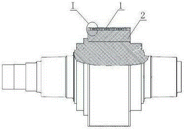
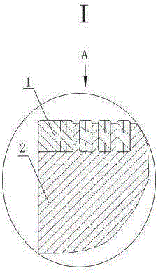
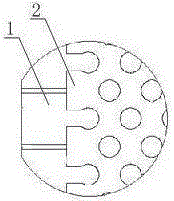
[0022] Such as figure 1 , 2 As shown in , 3, a side insert of a high-pressure roller mill roll cover, the side insert 1 is in the shape of a circle, and the side insert 1 is embedded in the outer surface of the roll cover 2 on both sides along the circumferential direction. In the annular groove, the annular groove is adapted to the radial cross-sectional shape of the side insert, and the side insert 1 and the annular groove are embedded and connected by a clearance fit; the side insert 1 is It is a circular structure composed of several inserts made of high-strength and wear-resistant hard alloy. Adjacent inserts are tightly bonded by adhesives. The adhesive loses its adhesion at 180-200°C. connection.

[0023] Such as Figure 4 As shown, a structure of the insert is as follows: it is integrally composed of a support part 3 and a protecti...


PUM


Abstract

The invention discloses a side insert of a roller shell of a high-pressure roller mill and a replacing method. The side insert is circle-shaped and is inserted in annular grooves respectively disposed at two side ends of the external surface of the roller shell along a circumference direction, and each annular groove is fit with radial section shape of the side insert; the side insert has a circle-shaped structure formed by splicing a plurality of inserts, and the adjacent inserts are bonded tightly by a bonding agent; and when the side insert needs to be replaced, the side insert is heated and the bonding agent loses viscosity, then an old side insert is replaced by a new side insert. The side insert has the advantages of being high in hardness, good in wear resistance, convenient to replace and long in service life, and also the side insert helps to alleviate wearing speed of a side shield and a lower side plate by giving indirect protection, and helps to prolong service life of the high-pressure roller mill.

Description

technical field [0001] The invention belongs to the technical field of high-pressure roller mills, and in particular relates to a side insert of a roller sleeve of a high-pressure roller mill and a replacement method. Background technique [0002] At present, the high-pressure roller mill is one of the intermediate equipment in the process of cement grinding and metal ore crushing. When crushing ore, in order to improve the rolling efficiency and prevent the material from overflowing in the cavity, a relatively sealed wall must be surrounded by two side baffles on the sides of the two roller sleeves. When the roller sleeve rotates at high speed, the two side baffles are tightly pressed on the side of the roller sleeve, causing a large amount of wear on the roller sleeve and the side baffle. Since the roller sleeve is made of high strength and hardness materials, the size It is also relatively large and heavy, and it is difficult to repair on site after wear and tear. In ord...

Claims


Application Information

Patent Timeline
Patent Type & Authority Patents(China)
IPC IPC(8): B02C4/30C09J5/00
Inventor 田鹤张光宇王亚强王素玲宋艾江王珂刚崔郎郎李聪杰丁建华张发展史宝龙
Owner CITIC HEAVY INDUSTRIES CO LTD
Learn More