
In-machine large-package cloth winding mechanism

A technology of large rolls and cloth rolling rollers, which is applied in the directions of winding strips, transportation and packaging, thin material processing, etc., which can solve the problems of glass fiber cloth slipping, reduced work efficiency, and increased labor intensity, etc., to reduce land occupation area, improve work efficiency, and avoid slipping

Active Publication Date: 2013-09-11
QINGDAO KAISHUO MACHINERY TECH CO LTD
View PDF7 Cites 4 Cited by
  • Summary
  • Abstract
  • Description
  • Claims
  • Application Information

AI Technical Summary

Problems solved by technology

However, this independent winding mechanism is only suitable for winding small and relatively light-weight cloth such as cotton yarn. Cloth, etc., because of its characteristics of hard, brittle, small friction coefficient, and easy slipping when coiling, if this independent coiling mechanism is used, because the package is too small, it is necessary to frequently disassemble the fabric coiling roller, resulting in labor The strength increases and the work efficiency decreases; in addition, because the cloth roll of this winding mechanism is set on one side of the frame, if the glass fiber cloth is wound, the glass fiber cloth will slip during the winding process due to slipping

Method used

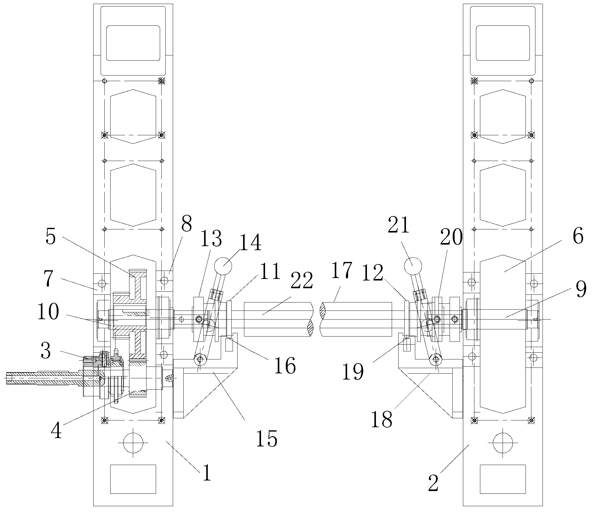

Image

  • In-machine large-package cloth winding mechanism

Examples


Embodiment Construction

[0019] The present invention will be further described in detail below in conjunction with the accompanying drawings and specific embodiments, but the present invention is not limited to these embodiments.

[0020] Such as figure 1 As shown, the large roll cloth rolling mechanism in the machine includes a frame, and the frame includes a left side frame 1 and a right side frame 2 with the same structure, and the left side frame 1 and the right side frame 2 A cloth rolling roller is arranged between them, and the cloth rolling roller includes a cloth rolling roller 17 and an air expansion shaft, and the air expansion shaft includes an air expansion cylinder 22, the left air expansion shaft shaft head 11 and the right air expansion shaft shaft head 12 , the inner cylinder of the cloth rolling roller 17 is detachably connected to the air expansion shaft; one end of the left air expansion shaft head 11 extends to the inside of the cloth rolling roller 17, and the other end is conne...


PUM


Abstract

The invention belongs to the technical field of textile machinery and discloses an in-machine large-package cloth winding mechanism which comprises a left side rack and a right side rack identical in structure. A cloth winding roller is arranged between the left side rack and the right side rack and comprises a cloth winding roller barrel and an air inflation shaft, the air inflation shaft comprises an air inflation barrel, a left side air inflation shaft head and a right side air inflation shaft head, the cloth winding roller barrel and the air inflation shaft are in detachable connection, one end of the left side air inflation shaft head extends into the inside of the cloth winding roller barrel while the other end of the same is connected with a left side guide shaft, one end of the right side air inflation shaft head extends into the inside of the cloth winding roller barrel while the other end of the same is connected with a right side guide shaft, the left side guide shaft and the right side guide shaft are arranged on the left side rack and the right side rack respectively and can transversely slide along the left side rack and the right side rack respectively, and a transmission mechanism is arranged on each of the left side rack and the right side rack and driven by a whole machine motor. By the in-machine large-package cloth winding mechanism, the grounding area of equipment is greatly reduced, the cloth falling mode is simple and quick, and production efficiency is improved.

Description

technical field [0001] The invention relates to a cloth rolling mechanism, in particular to an in-machine large-package cloth rolling mechanism, which belongs to the field of textile machinery. Background technique [0002] At present, the cloth rolling device used in production lines or equipments such as various cloths includes a frame, a cloth rolling roller, and a power drive mechanism that drives the cloth rolling roller to rotate, wherein the cloth rolling roller includes a roller and a roller shaft, and the roller and The roller shafts are fixed together. When removing the cloth roller from the frame or installing the cloth roller, the roller of the cloth roller is integrated with the roller shaft and cannot be disassembled. Great inconvenience will affect the improvement of production efficiency. [0003] Patent CN102756937A discloses an independent winding mechanism, which includes a frame, a cloth rolling roller, and a power drive mechanism that drives the cloth r...

Claims


Application Information

Patent Timeline
Patent Type & Authority Applications(China)
IPC IPC(8): B65H18/04
Inventor 邢桂松
Owner QINGDAO KAISHUO MACHINERY TECH CO LTD
Learn More