Cross-district double-U-shaped ventilating system for high-gas working face and application method for cross-district double-U-shaped ventilating system

A ventilation system and working face technology, which is applied in mine/tunnel ventilation, earthwork drilling, mining equipment, etc. It can solve problems such as high maintenance costs, roadways that cannot be used for the next working face, and reduced coal recovery rate in the mining area. , to achieve the effect of increasing the recovery rate

Inactive Publication Date: 2013-09-11
CHINA UNIV OF MINING & TECH
View PDF5 Cites 4 Cited by
  • Summary
  • Abstract
  • Description
  • Claims
  • Application Information

AI Technical Summary

Problems solved by technology

However, this double U-shaped ventilation system has the following two disadvantages: First, due to the influence of the mining of the working face, the gas discharge tailway retained by the mining face is extremely difficult to maintain, not only the maintenance cost is high, but also Sometimes the roadway cannot be used for the next working face; secondly, the coal pillar width of the gas discharge tail roadway and the working face is generally 10-35m, and the width of the coal pillar in the roadway is relatively large, which reduces the coal recovery rate in the mining area and causes coal waste of resources

Method used


Image

  • Cross-district double-U-shaped ventilating system for high-gas working face and application method for cross-district double-U-shaped ventilating system
  • Cross-district double-U-shaped ventilating system for high-gas working face and application method for cross-district double-U-shaped ventilating system
  • Cross-district double-U-shaped ventilating system for high-gas working face and application method for cross-district double-U-shaped ventilating system

Examples


Embodiment Construction

[0020] Specific embodiments of the present invention will be described in detail below in conjunction with the accompanying drawings.

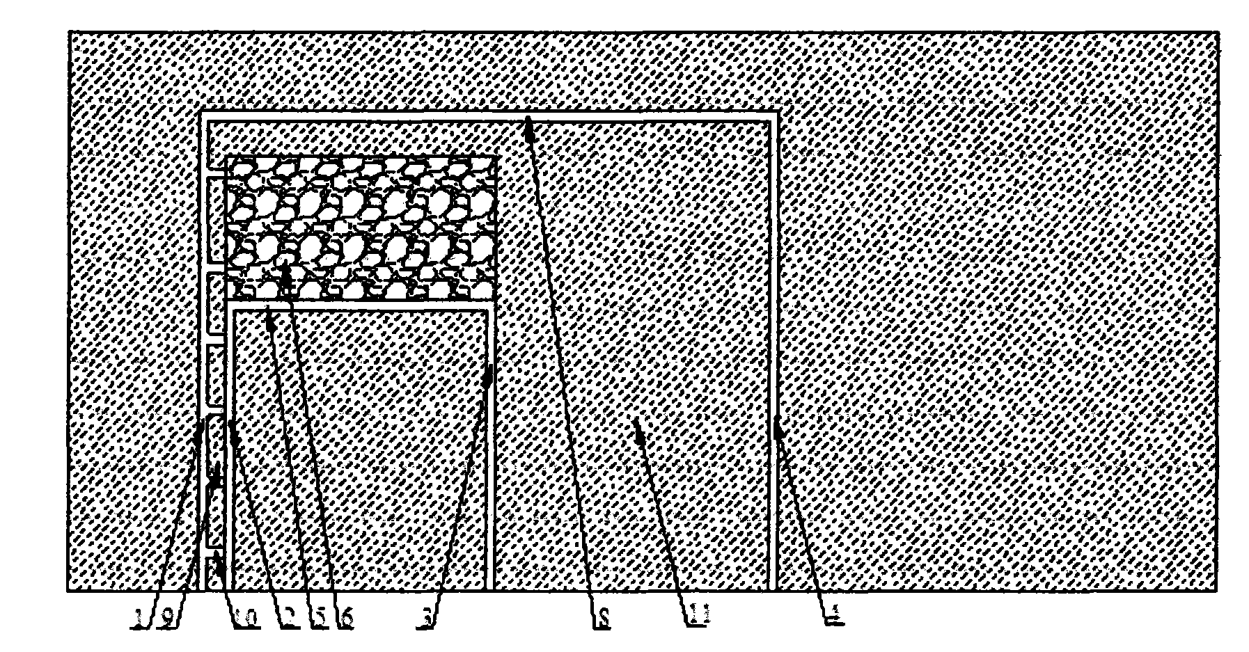
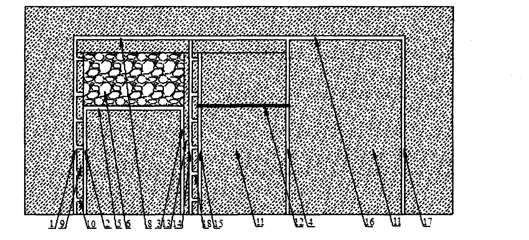
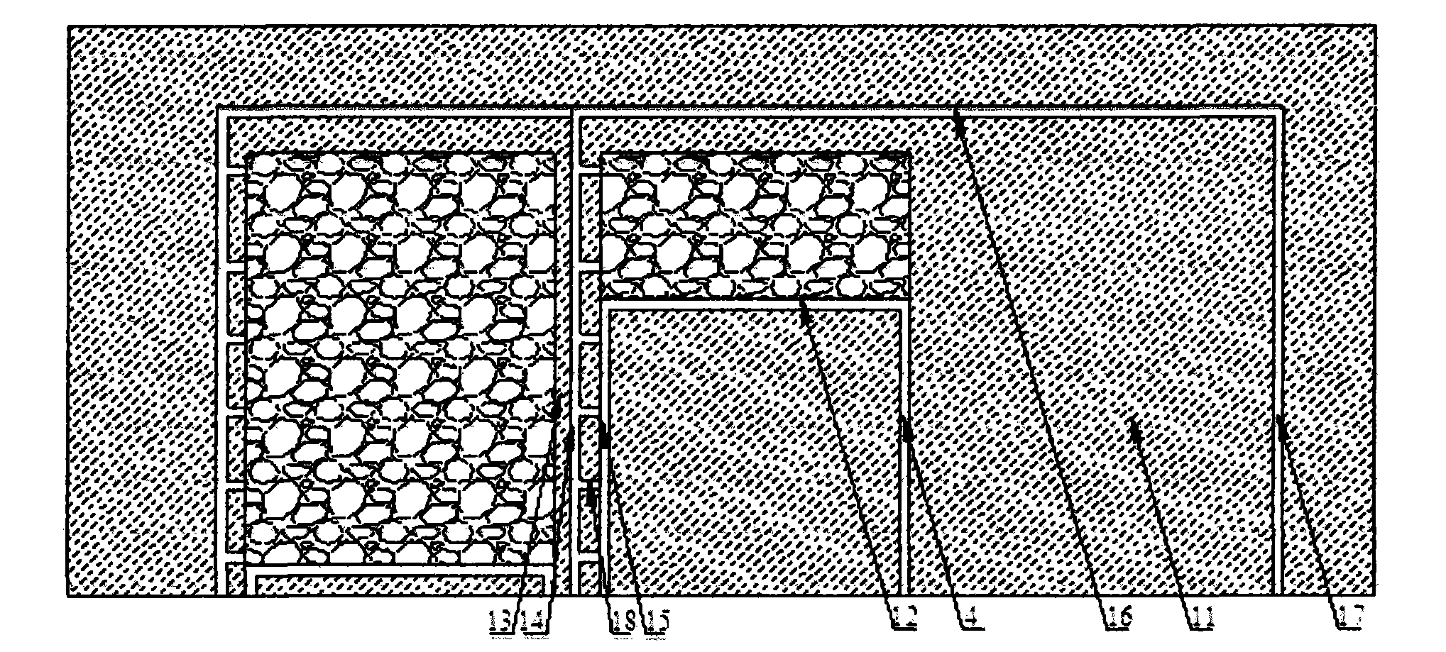
[0021] Such as figure 1 As shown, the cross-section double U-shaped ventilation system of the high-gas working face in this embodiment includes: the working face 5, the goaf 6 located above the working face, and the return gas tailgates arranged in sequence from left to right 1. Return air alley 2, air inlet alley 3 and air inlet tile exhaust alley 4 (four ventilation alleys with two inlets and two circuits). Both the air inlet lane 3 and the air return lane 2 are in communication with the working face 5 , thus constituting the inner U-shaped ventilation system of the working face 5 . The return air tile exhaust alley 1 and the air inlet tile exhaust alley 4 are arranged on both sides of the working face 5, and the two are connected through the auxiliary cutout 8, thereby constituting the outer U-shaped ventilation system of the working face ...


PUM


Abstract

The invention belongs to the field of mines, and relates to a cross-district double-U-shaped ventilating system for a high-gas working face and an application method for the cross-district double-U-shaped ventilating system. The working face is mainly served by an air inlet roadway, an air return roadway, an air inlet gas exhaust tail roadway and an air return gas exhaust tail roadway of the ventilating system, and the air inlet roadway is connected with the air return roadway by the working face, so that an inner U-shaped ventilating system is formed; the air return gas exhaust tail roadway is distanced from the outer side of the air return roadway by 5-20m, the air inlet gas exhaust tail roadway is distanced from the outer side of the air inlet roadway by 150-350m, and the two gas exhaust tail roadways form an outer U-shaped ventilating system by the aid of an auxiliary cut hole. The double-U-shaped ventilating system and the application method have the advantages that the problem of gas accumulation at upper corners and a gob of an existing high-gas working face is solved, an excellent stress environment is provided for roadway driving and maintaining by a cross-district huge coal-pillar entry protection process, the coal recovery rate of each district is increased by means of reducing the width of each coal pillar between the corresponding roadways, and social and economic benefits are obvious.

Description

technical field [0001] The invention relates to a layout method of a mining roadway in a high-gas working face, belongs to the technical field of ventilation of a high-gas working face, and in particular relates to a cross-section double U-shaped ventilation system of a high-gas working face and an application method thereof. Background technique [0002] At present, the ventilation of the working face is one of the many factors restricting the high production and high efficiency of high gas coal mines in my country. A better working face ventilation system can not only provide sufficient air supply but also ensure easy maintenance of the mining roadway and a high coal recovery rate in the mining area. In order to achieve the above requirements, many improvements have been made to the ventilation system of the high gas working face, including the following forms: [0003] The U+L ventilation system includes a U-shaped ventilation system and tail alleys at the same level wit...

Claims


Application Information

Patent Timeline
IPC IPC(8): E21F1/00
Inventor 徐营魏昌盛柏建彪
Owner CHINA UNIV OF MINING & TECH
Why Eureka
Try Eureka