Friction damper
A friction damper and outer ring technology, applied in the fields of vibration, earthquake control devices, and impact, can solve the problems of inability to adjust parameters, inability to adjust on site, complicated processing technology, etc., to achieve convenient adjustment of damping parameters, broad market application prospects, Good engineering practicability
- Summary
- Abstract
- Description
- Claims
- Application Information
AI Technical Summary
Problems solved by technology
Method used
Image
Examples
Embodiment 1
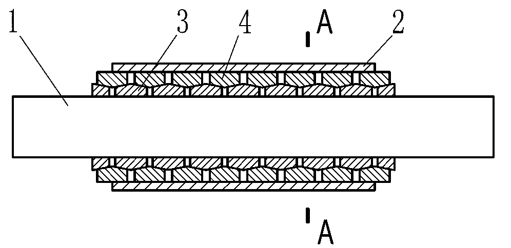
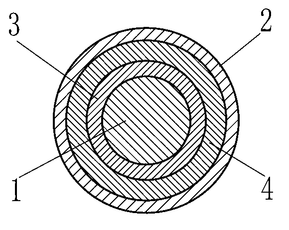
[0050] Such as figure 1 with figure 2 The friction damper of the present invention as shown includes a plunger 1 and a restraint cylinder 2, the plunger 1 is partially arranged in the restraint cylinder 2, and a group of combined expansion rings are arranged on the surface of the plunger 1, and the combined expansion ring consists of an inner tapered surface The outer ring 4 and the inner ring 3 with the outer tapered surface cooperate to form, and the inner wall of the constraint cylinder 2 is in close contact with the surface of the outer ring 4 .
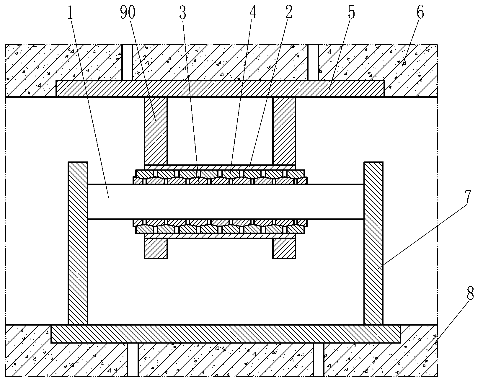
[0051] The working principle of the friction damper of the present invention will be described below by taking the application in bridge structures as an example, wherein the plunger 1 and the restraining cylinder 2 of the friction damper of the present invention are both made of steel, and the inner ring in the combined expansion ring 3 and outer ring 4 are all made of spring steel. Such as image 3 As shown, according to th...
Embodiment 2
[0059] Such as Figure 4 with Figure 5 The difference between the friction damper of the present invention shown in Embodiment 1 is that one end of the plunger 1 is set in the restraining cylinder 2, and in addition, pretensioning devices are provided on both sides of the combined expansion ring, and the pretensioning devices include steel The outer surface of the plunger 1 corresponds to two limit stops 11 which are respectively welded and fixed on both sides of the combined expansion ring. In addition, in order to facilitate the connection with the surrounding structures, the plunger and the restraining cylinder are respectively provided with connecting interfaces, which are specifically the connecting plate 10 welded on the plunger 1 and the connecting plate 9 welded and fixed on the restraining cylinder 2 . In addition, the combined expansion ring directly adopts the finished ring spring, and the ring spring is also composed of an outer ring 4 with an inner tapered surf...
Embodiment 3
[0066] Such as Figure 9 The difference between the friction damper of the present invention and the second embodiment is that the combined expansion ring includes a plurality of inner rings 3 and outer rings 4, the number of which is the same, and the inner rings 3 correspond to the outer rings 4 one by one. And superimposed on each other through the cooperation of the inner and outer cone surfaces, there is no gap between the adjacent outer rings and the adjacent inner rings, and the inclination direction of the inner cone surfaces of the adjacent outer rings is the same as that of the outer ring of the inner ring. The direction of inclination of the cone also remains the same. In addition, the plunger 1 is provided with a pretensioning device corresponding to both sides of the combined expansion ring, and the pretensioning device includes a limit stopper 11 fixedly welded on the surface of the plunger 1 and a limit pin 43 embedded in the plunger 1 . Wherein, a space compe...
PUM
 Abstract
Description
Claims
Application Information
 - R&D
- Intellectual Property
- Life Sciences
- Materials
- Tech Scout
- Unparalleled Data Quality
- Higher Quality Content
- 60% Fewer Hallucinations
Browse by: Latest US Patents, China's latest patents, Technical Efficacy Thesaurus, Application Domain, Technology Topic, Popular Technical Reports.
© 2025 PatSnap. All rights reserved.Legal|Privacy policy|Modern Slavery Act Transparency Statement|Sitemap|About US| Contact US: help@patsnap.com


