Supercharge Your Innovation With Domain-Expert AI Agents!

An optical cable transfer box

An optical cable transfer box and optical cable technology, which is applied in the field of optical communication, can solve problems such as wrong joints or missed connections, optical cables, optical fiber confusion, and reduced capacity of optical cable transfer boxes, and achieve orderly wiring, easy management and maintenance, and simple structure Effect

Inactive Publication Date: 2015-08-12
刘喜忠
View PDF4 Cites 0 Cited by
  • Summary
  • Abstract
  • Description
  • Claims
  • Application Information

AI Technical Summary

Problems solved by technology

However, after repeated expansion or maintenance of the optical cable transfer box, the optical cables and optical fibers in the optical cable transfer box will be confused, difficult to identify, and prone to misalignment or missing connections, which will cause inconvenience to subsequent construction. The capacity of the optical cable transfer box is artificially reduced

Method used


Image

  • An optical cable transfer box
  • An optical cable transfer box
  • An optical cable transfer box

Examples


Embodiment 1

[0013] Embodiment 1 of the present invention is an optical cable transfer box integrated with optical cable fusion:

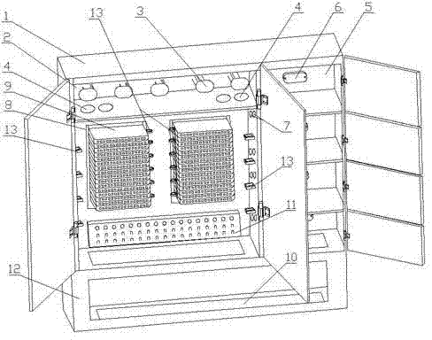
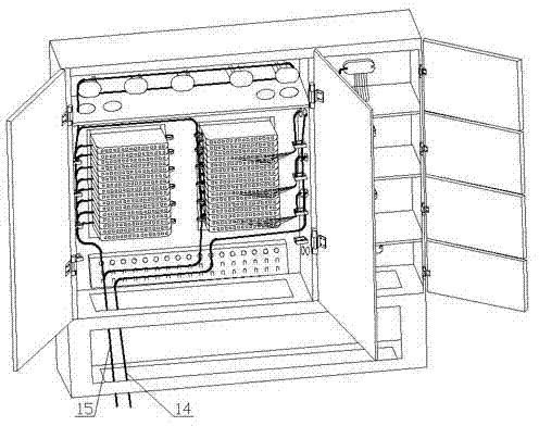
[0014] like figure 1 , figure 2 As shown, Embodiment 1 of the present invention includes: an optical cable transfer cabinet 1, a fiber tray frame 2, a fiber winding column 3, an optical fiber inlet and outlet hole 4, a fusion splice frame 5, a splice tray 6, a fusion through hole 7, and a fusion splicing integrated tray rack 8 , Welding integrated tray 9, inlet and outlet port 10, fixing seat 11, base frame 12, fixing clip 13, upper-level optical cable 14, lower-level optical cable 15;

[0015] Specifically, the optical cable transfer box with integrated optical cable fusion includes an optical cable transfer cabinet 1, at least one side of the optical cable transfer cabinet is connected with a disk fiber frame 2 reserved for output optical fibers, and the fiber disk frame 2 is provided with a A winding column 3 for winding reserved optical fibers, an op...

Embodiment 2

[0022] Embodiment 2 of the present invention provides an optical cable transfer box that can be used for triple play:

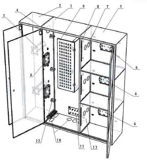
[0023] like image 3 , Figure 4 As shown, Embodiment 2 of the present invention includes: an optical cable transfer cabinet 1, a fiber coil frame 2, a fiber winding column 3, an optical fiber inlet and outlet hole 4, a fusion splice frame 5, a fusion splice tray 6, a fusion through hole 7, an optical fiber coupler 8, an optical fiber Adapter 9, inlet and outlet port 10, fixing seat 11, fixing clip 12, welding frame 13, optical cable 14, user optical fiber 15;

[0024] Specifically, the optical cable transfer box that can be used for the integration of the three networks includes an optical cable transfer cabinet 1, at least one side of the optical cable transfer cabinet 1 is connected with a coil frame 2 reserved for output optical fibers, and a fiber coil frame 2 is provided for winding. An optical fiber entry and exit hole 4 is provided on the partit...


PUM


Abstract

The invention relates to an optical cable cross connecting cabinet which comprises an optical cable cross connecting cabinet body. At least one peripheral side of the optical cable cross connecting cabinet body is connected with a fiber coiling frame for reserving of output optical fibers, fiber winding columns for winding reserved optical fibers are arranged in the fiber coiling frame, and optical fiber inlet and outlet holes are formed in a partition plate between the fiber coiling frame and the optical cable cross connecting cabinet body. A fusion welding frame is arranged on another peripheral side of the optical cable cross connecting cabinet body, a column of fusion welding discs used for fusion welding of optical fibers is arranged in the fusion welding frame, and fusion welding through holes are formed in a partition plate between the fusion welding frame and the optical cable cross connecting cabinet body. The optical cable cross connecting cabinet is provided with the fiber coiling frame specially used for coiling, storing and reserving optical fibers, and has the advantages of simple structure, orderliness of routing in the cabinet, capability of effectively protecting optical cables and optical fibers, convenience in management and maintenance and the like.

Description

technical field [0001] The invention relates to optical communication technology, in particular to an optical cable transfer box. Background technique [0002] In the optical cable access network, the optical cable transfer box provides optical cable termination and jumper function for the backbone layer and distribution layer optical cables, and becomes an important link in optical cable testing and dispatching. With the advancement of FTTB (Fiber To The Building) and FTTH (Fiber To The Home) construction, more and higher demands are put forward for optical cable transfer boxes for optical cable introduction, branching and branching. [0003] At present, the optical cable communication and the traditional copper cable communication are in the transition stage of the new and the old. When installing the optical cable transfer box, it is not sure whether the number of output fibers is sufficient. The optical cable transfer box often needs to be connected to new user optical f...

Claims


Application Information

Patent Timeline
Patent Type & Authority Patents(China)
IPC IPC(8): G02B6/44
Inventor 刘喜忠
Owner 刘喜忠
Features
  • R&D
  • Intellectual Property
  • Life Sciences
  • Materials
  • Tech Scout
  • Unparalleled Data Quality
  • Higher Quality Content
  • 60% Fewer Hallucinations
Learn More