Deskew display panel

A display panel and color shift technology, applied in static indicators, nonlinear optics, instruments, etc., can solve problems such as easy color shift, achieve the effect of suppressing color shift and improving color display effect

Active Publication Date: 2013-09-11
SHENZHEN CHINA STAR OPTOELECTRONICS TECH CO LTD
View PDF4 Cites 15 Cited by
  • Summary
  • Abstract
  • Description
  • Claims
  • Application Information

AI Technical Summary

Problems solved by technology

[0003] The present invention aims at the defect that the existing display panel is prone to color shif...

Method used


Image

  • Deskew display panel
  • Deskew display panel
  • Deskew display panel

Examples


Embodiment Construction

[0059] Hereinafter, the present invention will be described in detail through the accompanying drawings and specific embodiments.

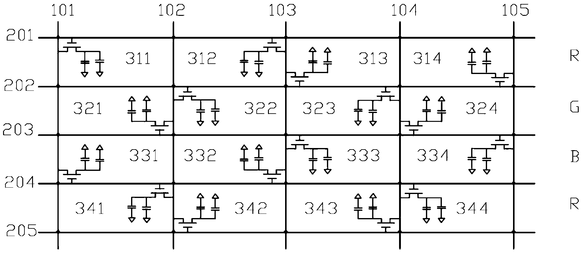
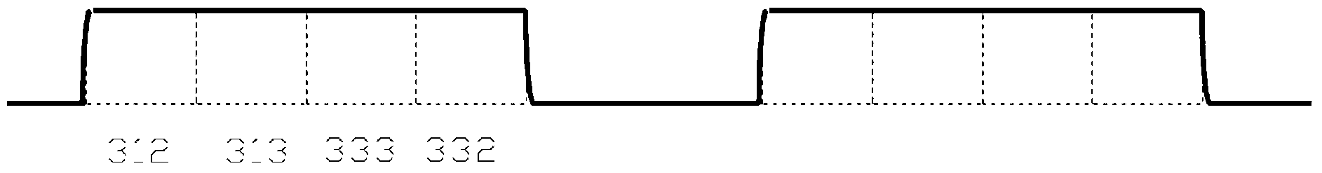
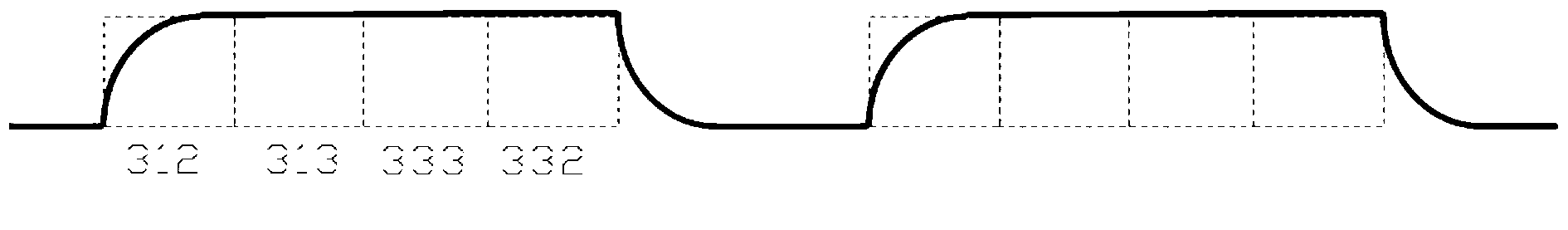
[0060] The scheme adopted in the present invention is to use m×n sub-pixels as a pixel unit, and the connection mode of the sub-pixel transistors at corresponding positions in each pixel unit is the same. When the data line Dn is connected to the source of the sub-pixel Pmn of one row in the pixel unit, it will be connected to the sources of two adjacent sub-pixels Pmn and Pmn-1 at the same time, and the gates of these two sub-pixels are connected respectively to two adjacent scanning lines Gm and Gm+1. In this way, when the data line charges the sub-pixels, it can always charge two adjacent sub-pixels at the same time. Even if there is an RC delay on one sub-pixel, resulting in color distortion, but this amount of distortion accounts for a small part of the entire color mixing, which can effectively suppress color cast.

[0061]Such as figure ...


PUM


Abstract

The invention relates to a deskew display panel comprising transverse scanning lines, longitudinal data lines and sub-pixels. The sub-pixels are distributed between the adjacent scanning lines and the data lines in arrays, and each mXn sub-pixels form a pixel unit. Each sub-pixel comprises a transistor, a grid of the transistor is connected with the scanning lines, a source electrode is connected with the data lines, and a drain electrode is respectively connected with two capacitors. Corresponding transistors of the sub-pixels of each pixel unit are connected in the same way. The data lines connected with the source electrodes in the pixel units are respectively connected with the two adjacent sub-pixels in a same row, and the source electrodes of the two sub-pixels are respectively connected to the upper and lower scanning lines. During color blending, skew degree is effectively suppressed, color display effect of the display panel is improved, and the deskew display panel is particularly applicable to a narrow-frame display.

Description

technical field [0001] The present invention relates to display technology, more specifically, to an anti-color shift display panel. Background technique [0002] A liquid crystal display panel is usually composed of a plurality of liquid crystal cells, and the display effects of these liquid crystal cells are controlled by transistors. Usually these transistors are sequentially turned on by the scan signal according to the sequence of rows and columns. In the traditional Trigate LCD panel, in order to save costs, the transistor source side (source) often adopts a high pin count (high pin count) design, for example, only one set of output terminals ( fanout) and a chip (IC), such a fanout resistance difference (Rmax-Rmin) is generally relatively large. In actual work, the difference in impedance is too large, and it is easy to cause color shift on both sides of the display panel when displaying a mixed color picture, that is, the displayed color deviates from the original ...

Claims


Application Information

Patent Timeline
IPC IPC(8): G02F1/1362G09G3/36
CPCG02F1/136286G02F1/136213G09G3/3648G09G2300/0426
Inventor 杜鹏姜佳丽
Owner SHENZHEN CHINA STAR OPTOELECTRONICS TECH CO LTD
Why Eureka
Try Eureka