
Color liquid crystal display device

a liquid crystal display and liquid crystal technology, applied in liquid crystal compositions, instruments, chemistry apparatus and processes, etc., can solve the problems of low light utilization efficiency, high power consumption of backlights or front lights, and low light utilization efficiency

Inactive Publication Date: 2009-10-06
CANON KK
View PDF33 Cites 4 Cited by
  • Summary
  • Abstract
  • Description
  • Claims
  • Application Information

AI Technical Summary

Benefits of technology

[0032]A specific object of the present invention is to provide a color liquid crystal display device capable of effecting good color display while suppressing temperature dependence of an amount of birefringence.

Problems solved by technology

On the other hand, as a disadvantage of the micro-color filter method, a transmittance is ⅓ of a monochromatic display method, so that a light utilization efficiency is low.
This low light utilization efficiency leads to a high power consumption of a back light or a front light in a transmission-type liquid crystal display apparatus having the back light or a reflection-type liquid crystal display apparatus having the front light.
The ECB-type liquid crystal display device is capable of effecting color display but has such a disadvantageous characteristic that a display characteristic is sensitively changed with respect to temperature.
As a result, color display with a good reproducibility cannot be effected, so that the disadvantageous characteristic has become an obstacle when a product of the display device is applied.
Further, the ECB-type liquid crystal display device has accompanied with such a disadvantage that the number of displayable colors.
The change in color is more sensitive to human's eyes than the change in brightness, so that this is a remarkably disadvantageous characteristic compared with the case of the ordinary color liquid crystal display device.
However, when the cell thickness is excessively large, a response speed of liquid crystal is slow, so that the liquid crystal display device is not practically suitable.

Method used


Image

  • Color liquid crystal display device
  • Color liquid crystal display device
  • Color liquid crystal display device

Examples


modified embodiment

[0094]In the above described embodiments, analog gradation is realized by the color filter with respect to green display and digital gradation is realized, during display of red and blue, by utilization of the coloring phenomenon based on the ECB effect and the display method based on the pixel division method with respect to red and blue. The above described embodiments may suitably be applied to the use of high definition display device in order to provide a sufficient gradation characteristic even at the limited number of gradation levels with respect to display of red and blue.

[0095]On the other hand, in the reflection-type liquid crystal display device as described above, there is also a use requiring a high transmittance and more display colors. Further, in the transmission-type liquid crystal display device capable of effecting full-color display, there have also been a requirement with respect to a high-transmittance display mode in order to suppress the power consumption of...

modified embodiment 1

Method (1) Utilizing ECB Effect-Based Coloring Phenomenon at Retardation Other than Those for Red and Blue

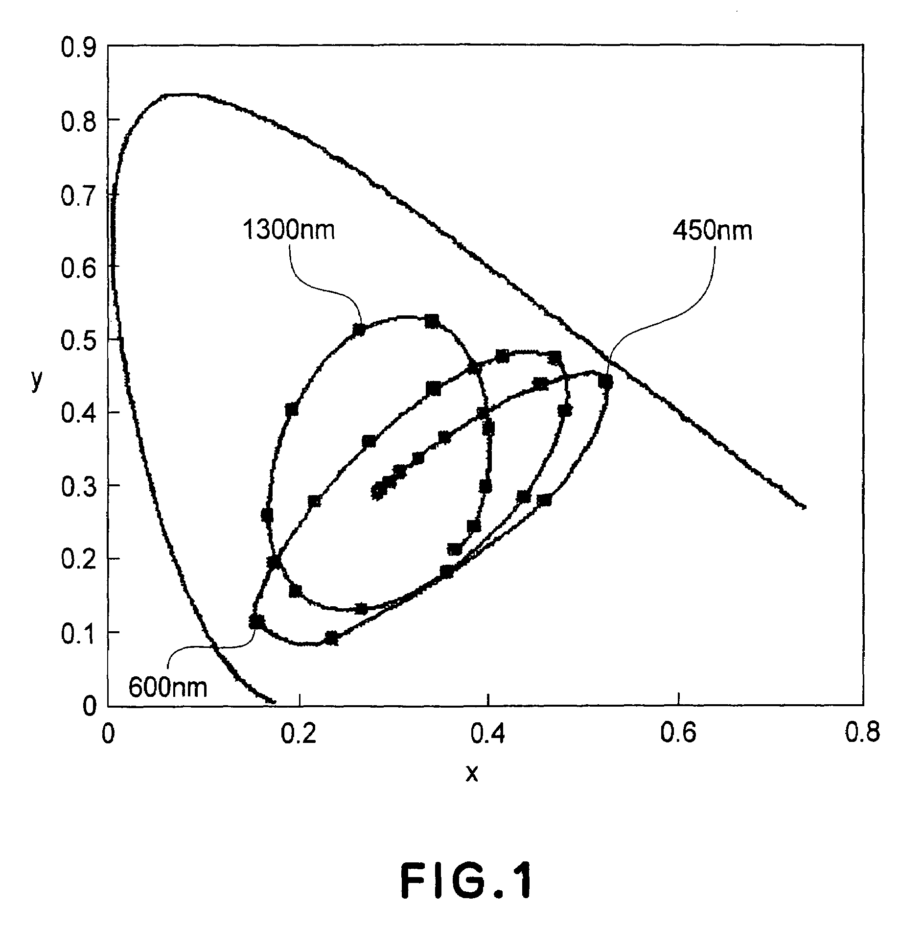
[0101]In the above described embodiment, the principle of effecting the display of red and blue by utilizing the coloring phenomenon on the basis of the ECB effect. In the coloring phenomenon based on the ECB effect, as shown in FIG. 8, it is possible to change the hue continuously from white to blue. More specifically, there are many available display colors other than red and blue described above. By using such display colors, it becomes possible to represent display colors larger in number than those described above.

[0102]More specifically, a change in display color under the above described cross-nicol condition in such a constitution that the first sub-pixel is not provided with the color filter will be described. As shown by the arrows indicated in FIG. 8, such a change in brightness of achromatic color that the display state is changed from the black state to the white st...

modified embodiment 2

Method (2) Utilizing Continuous Gradation Color in Low Retardation Range at Pixel Provided with Color Filter of Color Complementary to Green

[0105]In the case where the first sub-pixel is no provided with the color filter as in the above described basic embodiment and Modified Embodiment 1, in a retardation range exceeding the white range, such a change in hue in the order of yellow, yellowish red, red, reddish violet (magenta), violet, bluish violet, and blue is achieved. In this modified embodiment, the first sub-pixel to be colored by the retardation change is provided with a color filter of color, such as magenta, complementary to green. As a result, it becomes possible to considerably enlarge the color reproduction range of red and blue.

[0106]FIGS. 5(c) and 5(d) show pixel constitutions in this modified embodiment. A G pixel 51 is provided with a green color filter similarly as in the basis embodiment. Further, first sub-pixels 52 and 53, which are transparent in the basic embod...


PUM

PropertyMeasurementUnit
thicknessaaaaaaaaaa
thicknessaaaaaaaaaa
thicknessaaaaaaaaaa

Abstract

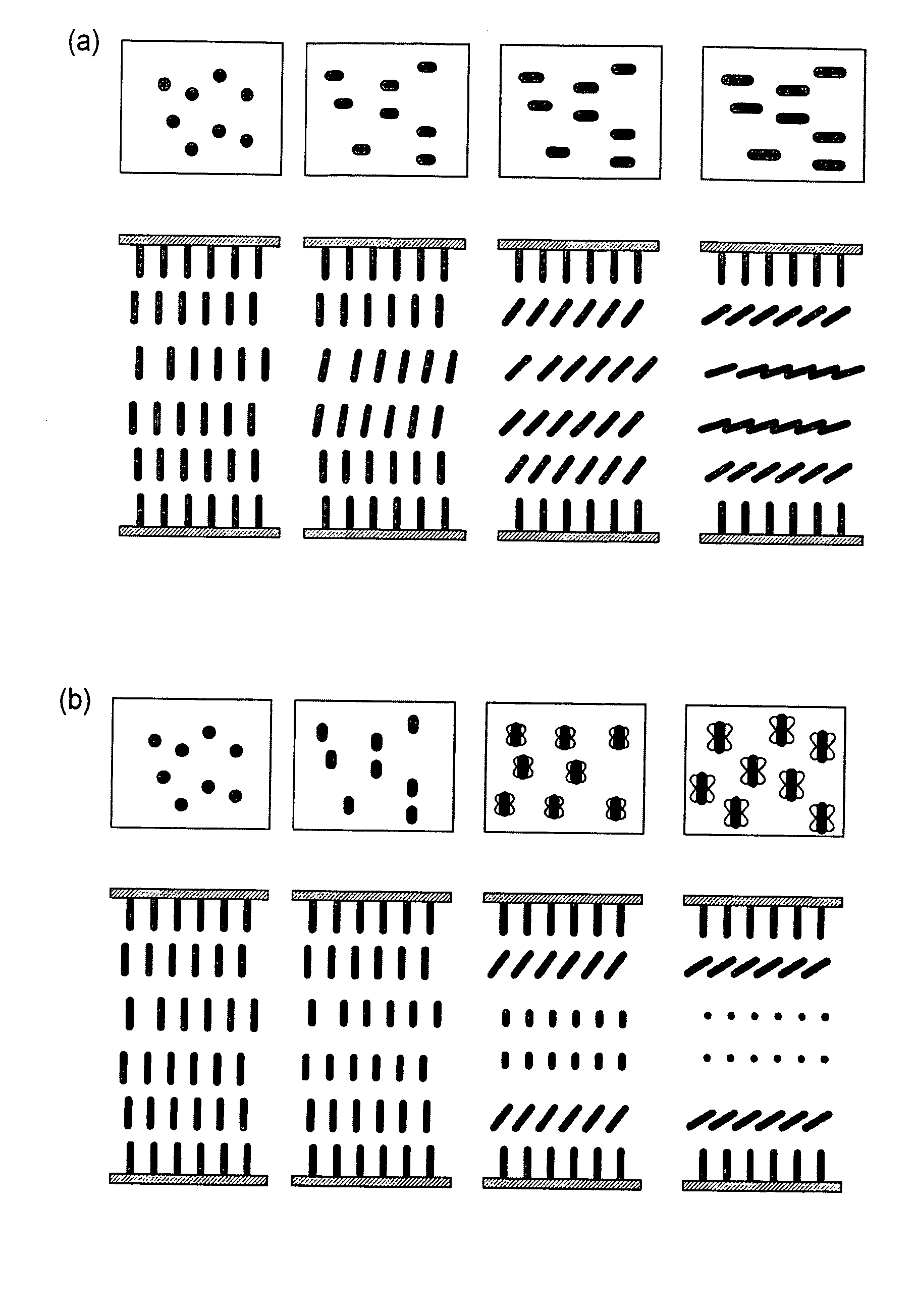
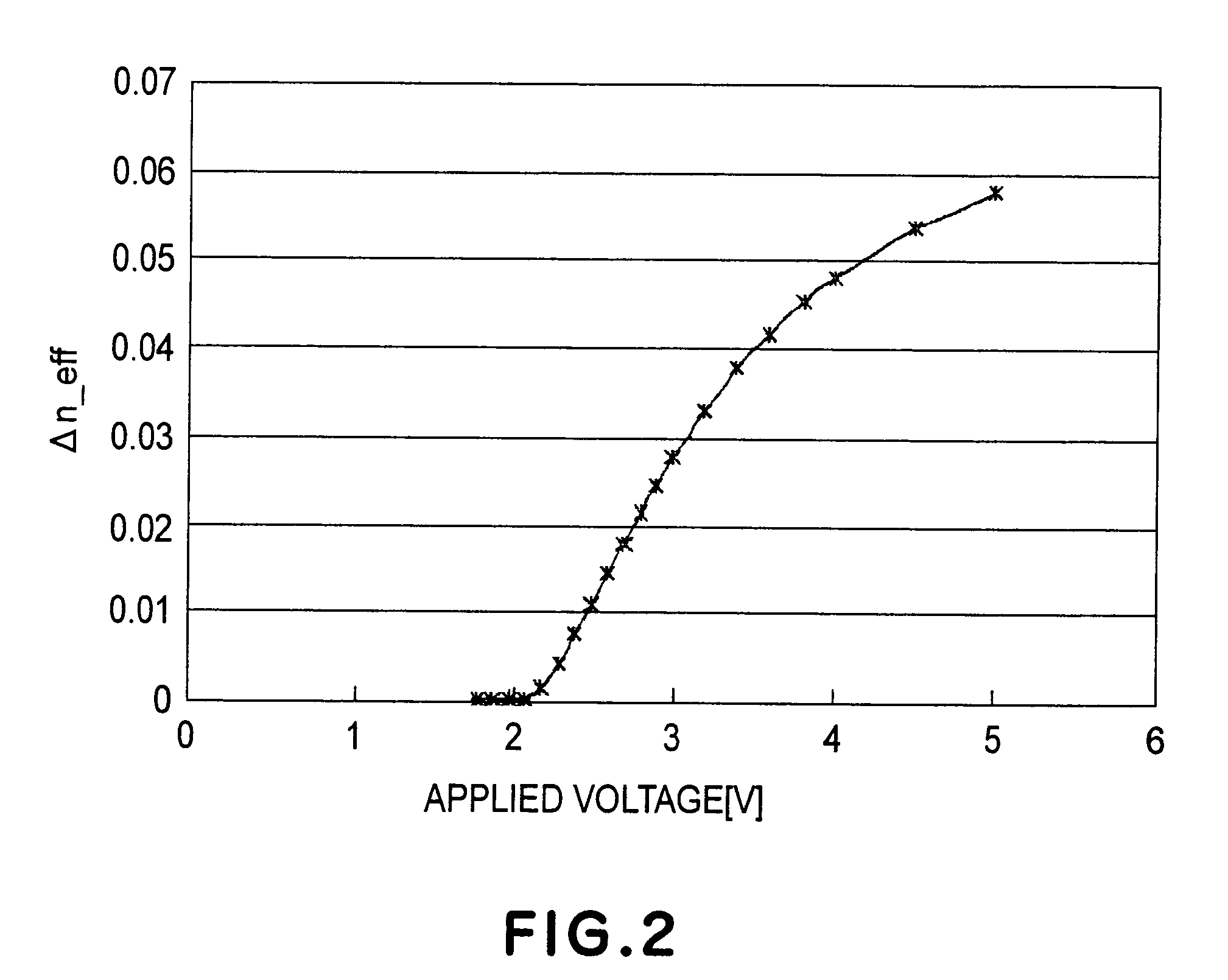
A color liquid crystal display device includes a pair of oppositely disposed substrates each of which is provided with an electrode and has been subjected to homeotropic alignment treatment, and chiral nematic liquid crystal disposed between the pair of oppositely disposed substrates. The chiral nematic liquid crystal is capable of causing birefringence leading to a change in brightness and a change in hue depending on a voltage applied between the electrodes. The liquid crystal is twistedly aligned under electric field application to change a twisted angle, so that a fluctuation in birefringence with temperature is compensated.

Description

FIELD OF THE INVENTION AND RELATED ART[0001]The present invention relates to a color liquid crystal display device capable of effecting multi-color display.[0002]At present, a flat-panel display has widely been popularized as various monitors for a personal computer and the like and as a display device for a cellular phone, and so on. In the future, the flat-panel display is expected to follow popularization more and more, such as development in use for big-screen television.[0003]A most popular flat-panel display is a liquid crystal display. As a color display method for the liquid crystal display, one called a micro-color filter method has been used widely.[0004]The micro-color filter method effects full-color display by constituting one unit pixel with at least three pixels and providing the three pixels with color filters of three primary colors of red (R), green (G), and blue (B), respectively, thus having an advantage of readily realizing a high color-reproducing performance.[...

Claims


Application Information

Patent Timeline
Patent Type & Authority Patents(United States)
IPC IPC(8): C09K19/02G02F1/1337G02F1/1335G02F1/136G02F1/139
CPCG02F1/1393G02F1/133514G02F2203/34G02F1/137
Inventor ASAO, YASUFUMI
Owner CANON KK
Learn More