Support clip for high current switch flipping

A technology of high-current switch and support clip, which is applied in the direction of open busbar installation, etc., can solve the problems of production workers such as skin allergies, rough cutting surface, and difficult processing, and achieve the effect of eliminating hidden dangers of skin allergies, improving cost performance, and beautiful layout

CN103296625BActive Publication Date: 2015-11-18YANGZHOU SENYUAN ELECTRIC
5 Cites 0 Cited by

Patent Information

Authority / Receiving Office
CN · China
Patent Type
Patents(China)
Current Assignee / Owner
Publication Date
2015-11-18

Smart Images

  • Figure 1
    Figure 1
  • Figure 2
    Figure 2
Patent Text Reader

Abstract

The invention discloses a support clip for a double-row large-current switch. The support clip for the double-row large-current switch is characterized by comprising a metal installation beam 1, an A support clip 2, a limiting groove 3, a bolt hole 4, a protruding cylinder 5, a reinforcing rib 6, a vertically clamping notch 7, a B support clip 8, a cylindrical sleeve 9, a clamping edge 10, an installation bolt 11 and a check nut 12. The support chip for the double-row large-current clip has the advantages of 1) being capable of randomly assembling and installing 3(4) pole insulating support clips according to wiring pile tips with different phase differences of various types of frame circuit breakers by adopting single phase stack mounting; 2) being capable of being formed in one step without any machining due to the fact that the support clip is formed by thermosetting plastics in a pressing mode and being capable of eliminating safety hazards of skin allergy of manufacturing workers; 3) adopting the clamping structure which totally meets the requirements of electric clearance and creep distance of a low-voltage distribution cabinet; and 4) having the cost which occupies about 2 / 5 of an original insulating installation strip made of epoxy resin plates, being reasonable to install, enabling the inner distribution of the distribution cabinet to be attractive and improving cost performance of the technology.
Need to check novelty before this filing date? Find Prior Art

Description

technical field

[0001] The supporting clip for turning over the high-current switch is used for supporting the vertical busbar connected between the switch and the horizontal busbar for switches of 3200A and above in the main cabinet of the incoming line of the low-voltage power distribution cabinet. It belongs to the field of design and manufacture of special devices for low-voltage power distribution cabinets. Background technique

[0002] The connection between 3200A and above high-current switches and horizontal busbars in low-voltage power distribution cabinets usually adopts more than two rows of vertical busbars. Since there is a space distance of more than 500mm between the switch pile head and the horizontal busbars, the vertical busbars have a distance of more than 500mm in this space. There needs to be a support point in the center, otherwise it will not be able to withstand the impact of high-current electric power. In the connection between the switch and the h...

Examples

Embodiment Construction

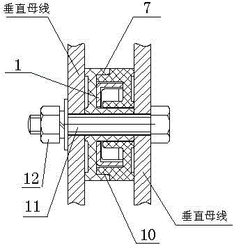
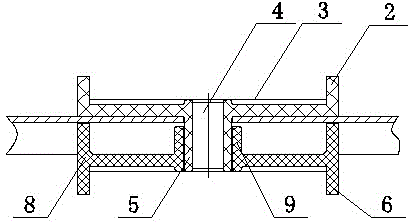
[0010] Referring to the accompanying drawings, its structure includes a metal mounting beam 1, A supporting clip 2, a limit groove 3, a bolt hole 4, a protruding cylinder 5, a reinforcing rib 6, an upper and lower engaging notch 7, a B supporting clip 8, and a cylindrical sleeve Cylinder 9, embracing side 10, mounting bolt 11, and tightening nut 12; A side surface of support clip 2 is provided with a limit groove with a width of more than 80mm for placing a copper busbar with a width of more than 80mm. There are bolt holes 4 for clamping on the side of the clamp, and the upper and lower ends of the limit groove 3 are provided with reinforcing ribs 6 to prevent deformation of the parts; the other side of the A support clamp 2 is provided with a cylindrical bolt hole. Sleeve 9, this cylindrical sleeve 9 should be able to match the outer diameter of the protruding cylinder 5 of the B support clip.

[0011] On the periphery of the cylindrical surface of the A support clip 2, there...