
PON (passive optical network) line fault monitoring method and device based on optical mark method

A technology for optical marking and line failure, applied in the field of optical fiber communication, can solve the problems of difficulty, reduced accuracy and operability, limited user capacity of passive optical network PON system, etc., and achieves the effect of high monitoring accuracy and low loss

Inactive Publication Date: 2013-09-11
GUANGXI NORMAL UNIV
View PDF4 Cites 20 Cited by
  • Summary
  • Abstract
  • Description
  • Claims
  • Application Information

AI Technical Summary

Problems solved by technology

Although the device can also detect the disconnection of the optical fiber loop in the passive optical network PON system, but in the case of many optical fiber branches, fiber gratings with different reflection wavelengths are placed, which will limit the performance of the passive optical network PON. System user capacity
In addition, this monitoring method depends on the measurement accuracy and wavelength range of the optical power meter, and has high requirements on the performance of the optical power meter. Therefore, if an optical power meter with a single function can extract each The corresponding monitoring data of the optical fiber loop is quite difficult
This solution will gradually reduce its accuracy and operability with the increase of the optical fiber loop in the passive optical network PON system

Method used

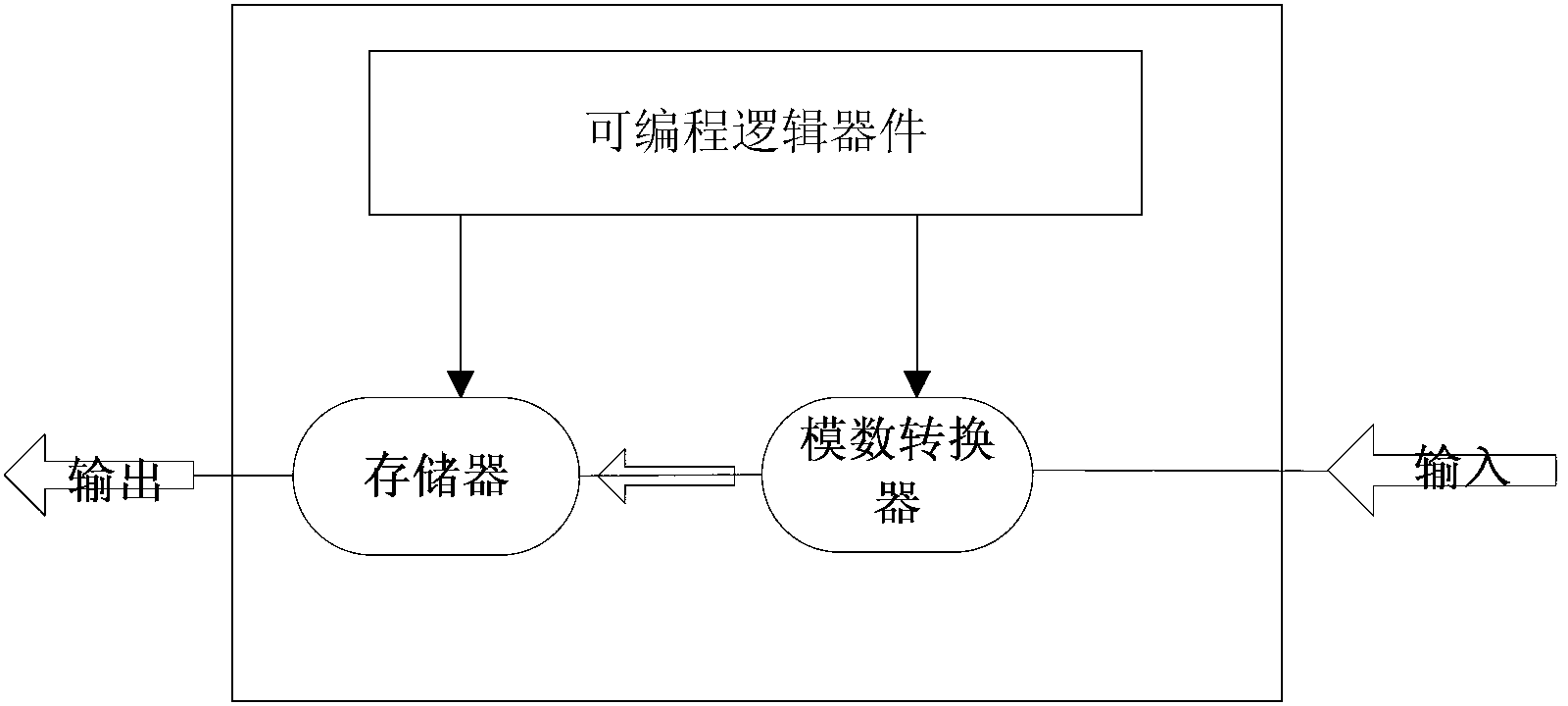

Image

  • PON (passive optical network) line fault monitoring method and device based on optical mark method
  • PON (passive optical network) line fault monitoring method and device based on optical mark method
  • PON (passive optical network) line fault monitoring method and device based on optical mark method

Examples


Embodiment Construction

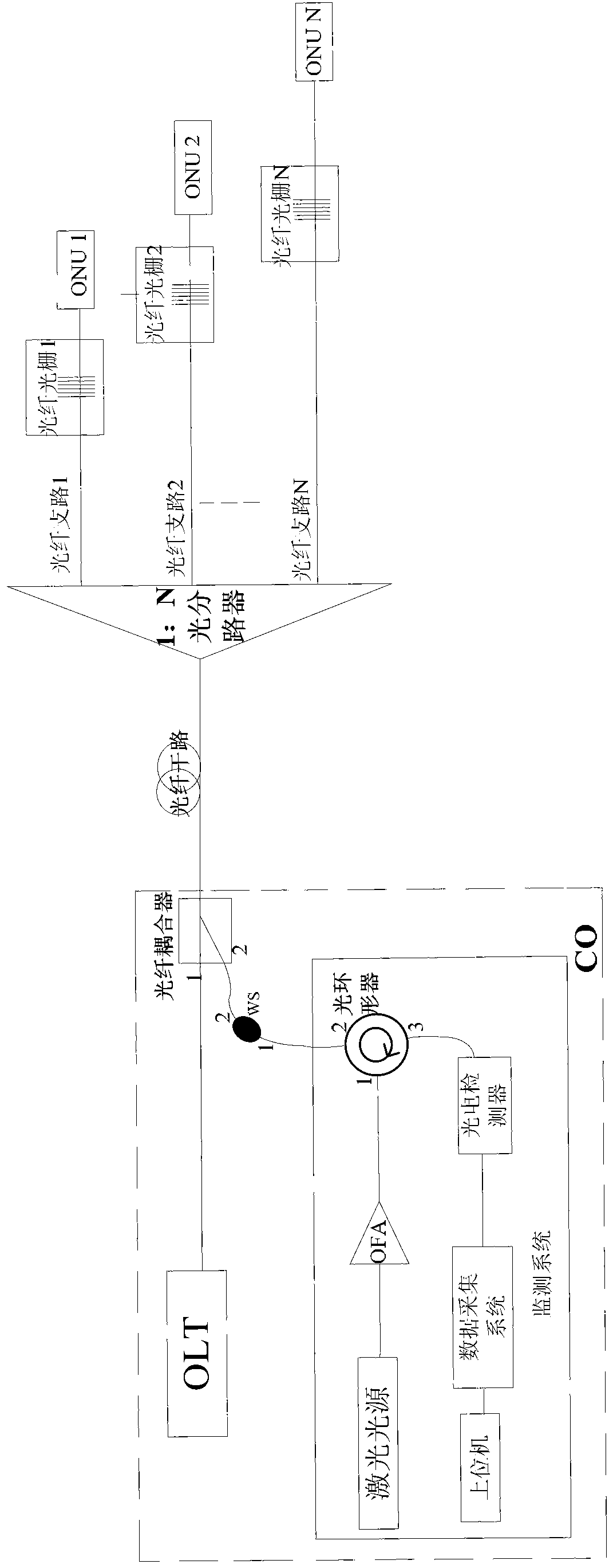
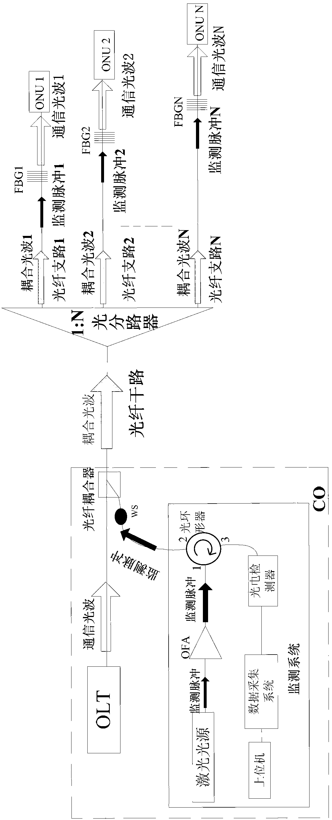
[0053] A PON line fault monitoring device based on optical marking method, such as figure 1 As shown, it includes monitoring system, wavelength selector (WS), 1:2 fiber coupler, 1:N optical splitter and N fiber gratings. The number of N is the same as the number of optical network units (ONUs) to be monitored. The value of N can be infinite in theory, but in consideration of practical effects, in the present invention, the range of N is any value from 2 to 128. In the present invention, the monitoring system, the wavelength selector 1:2 fiber coupler and the optical network unit are all arranged in a central office (CO).

[0054] The input and output ports of the above-mentioned monitoring system share one interface, which is mainly composed of a laser light source, an optical fiber amplifier, an optical circulator, a photoelectric detector, a data acquisition system and a host computer. The output end of the laser light source is connected to the first port of the optical c...


PUM


Abstract

The invention discloses a PON line fault monitoring method and device based on an optical mark method. The device comprises a monitoring system, a wavelength selector, a 1: 2 optical fiber coupler, a 1: N optical branching device and N FBGs (fiber bragg grating). The distance between the FBG connected in series to every optical fiber branch and the optical branching device is different, so that the transmission time of narrow-band monitoring pulses, which are transmitted by a laser light source, on every optical fiber branch is different, and further the monitoring pulses on the optical fiber branches can be arranged in sequence in time domain. Due to the fact that the monitoring pulses arriving at the branches are marked in time domain to distinguish feedback signals of different lines, the method is called as the optical mark method. An upper computer compares received monitoring pulse data with original data and determines the on-off state of the corresponding branch through the existence and inexistence of certain pulses. The PON line fault monitoring method and device effectively overcomes the difficulty that an OTDR (optical time domain reflectometry) cannot support multi-branch network monitoring; is a simple and practical real-time monitoring method for large-branch-ratio optical network lines; and has the advantages of high precision and operation convenience.

Description

technical field [0001] The invention belongs to the technical field of optical fiber communication, and in particular relates to a PON line fault monitoring method based on an optical marking method and a device thereof. Background technique [0002] "Fiber into copper back" is an inevitable trend in the development of broadband access technology. With the expansion of PON (Passive Optical Network, Passive Optical Network) coverage, real-time monitoring of its line faults becomes particularly important. PON has the characteristics of many line branches, complex structure and easy to be affected by the geographical distribution of users, which increases the complexity of its line maintenance and management. The splitting ratio of the next-generation PON technology will reach 1:128, and there is an urgent need for an optical layer automatic monitoring solution that effectively supports networks with a large splitting ratio. Optical fiber line faults account for a large propo...

Claims


Application Information

Patent Timeline
Patent Type & Authority Applications(China)
IPC IPC(8): H04B10/071H04Q11/00
Inventor 李传起王大迟胡金林陈艳杨梦婕陈美娟
Owner GUANGXI NORMAL UNIV
Learn More