

Method and apparatus for detecting crack formation in lifting members and lifting frame
A technology for lifting frames and components, which is applied in the measurement, measurement of force, and tension measurement of the change force of the optical properties of the material when it is stressed, and can solve the problems of container falling off, too frequent, twist lock damage, etc., to achieve and The effect of compact equipment and reliable equipment
- Summary
- Abstract
- Description
- Claims
- Application Information
AI Technical Summary
Problems solved by technology
Method used
Image

Examples
Embodiment Construction
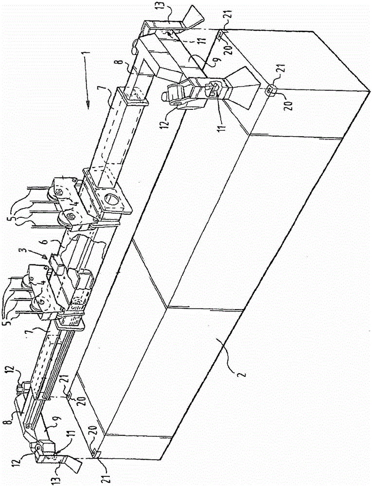
[0028] A lifting frame or spreader 1 for transporting a container 2 is suspended from a container crane by means of a cable 5 pulled around a pulley 4 . The lifting frame 1 includes a central beam 6 , two extendable middle beams 7 and two extendable outer beams 8 . Each outer beam 8 supports a cross beam 9 defining two corner points 12 . Lifting members or twist locks 11 engaging in openings 20 in corner castings 21 of the container 2 are provided at these corner points 12 of the lifting frame 1 . A pivotable guide member or flipper 13 is also provided at the corner point 12 .
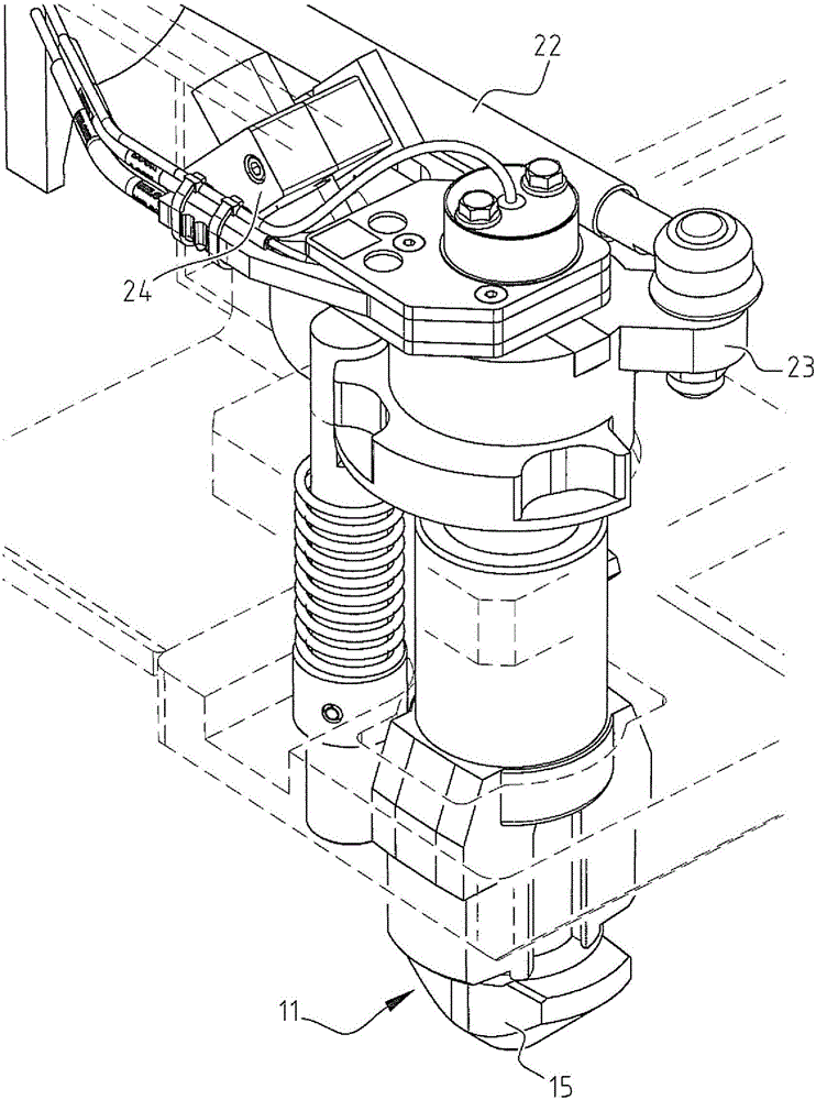
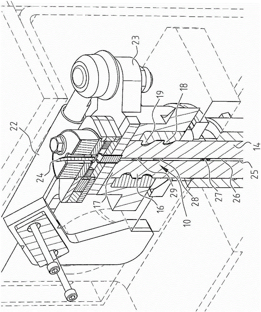
[0029] Each lifting member 11 is substantially T-shaped and has a shaft 14 and a hammer head 15 . Two grooves and thus two collars or shoulders 16, 17 are formed on the upper side of the shaft 14, so that the lifting member 11 is suspended on a shoulder which also has two grooves and two collars 18, 19. ring support element. These two collars form redundant paths for forces as described in EP138577...
PUM
 Abstract
Description
Claims
Application Information