
Subjective optometry instrument and optometry method

A refractometer, subjective technology, applied in the field of human eye optometry, can solve problems such as complex structure, inability to be used as self-examination, and high price

Active Publication Date: 2013-09-18
SHENZHEN CERTAINN TECH CO LTD
View PDF6 Cites 14 Cited by
  • Summary
  • Abstract
  • Description
  • Claims
  • Application Information

AI Technical Summary

Problems solved by technology

However, traditional optometry equipment is complex in structure, requires doctors to operate, and is expensive. It is difficult to popularize in families and communities, and it cannot be used as a tool for self-examination.

Method used


Image

  • Subjective optometry instrument and optometry method
  • Subjective optometry instrument and optometry method
  • Subjective optometry instrument and optometry method

Examples


Embodiment 1

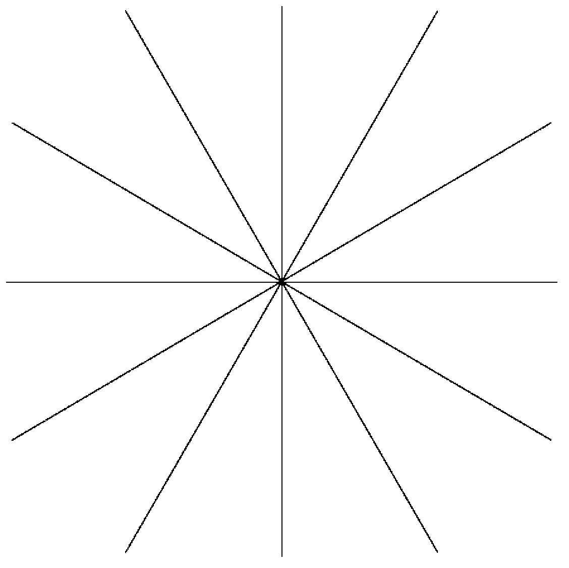
[0109] The marker 101 can be a picture with stripes of different orientations or radiation similar to a traditional astigmatism meter. In the description below, the radiation (marked on the marker symbol, radial) as an example.

[0110] When the marker moves to a certain position x, the marker When the lines in all directions are clear at the same time, the spherical power of the testee is D 1 =x / f 0 2 , at this time, the subject has no astigmatism or the astigmatism is negligible, and the cylinder degree is 0.

[0111] when marker When the lines in all directions are not clear at the same time, there are two positions that make the two perpendicular radial lines clear;

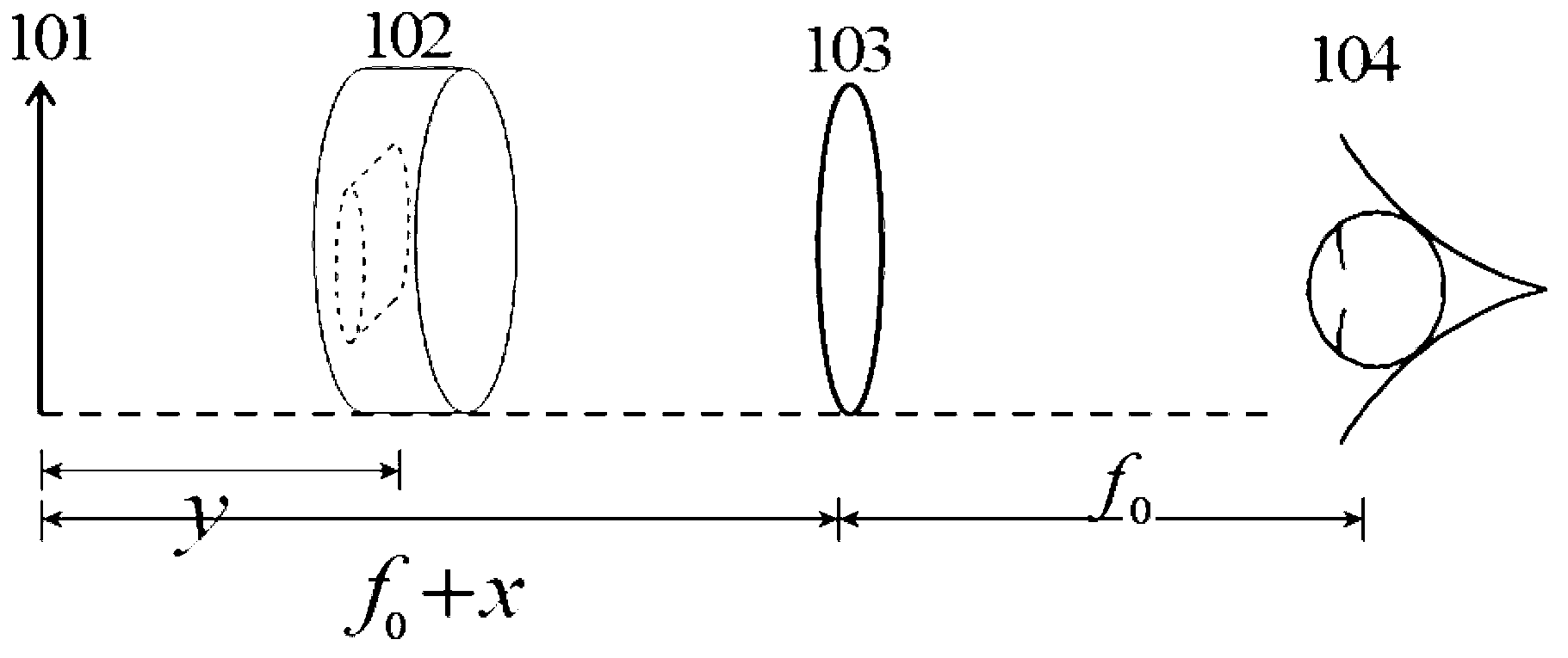
[0112] refer to figure 1 , during measurement, the marker 101 moves back and forth, if there are two positions where the lines in a certain direction of the radiation can be clearly seen, and the radiations in the two directions are perpendicular to each other, then

[0113] For the first position,...

Embodiment 2

[0128] Likewise, the marker 101 can be a picture, with stripes of different orientations or radiation similar to a traditional astigmatism meter. In the description below, the radiation (marked on the marker symbol, radial) as an example. This embodiment utilizes the cylindrical lens 102, and the cylindrical lens 102 and the marker 101 overlap together and move back and forth. There are also two situations:

[0129] When the subject can clearly see the marker at a certain position x All the lines in the symbol, the spherical power of the subject can be calculated according to the calculation method of the spherical power above, and it can be known that the tested human eye has no astigmatism.

[0130] When moving to certain two positions, the subject can clearly see the marker When one of the two perpendicular lines in the symbol is clear, the spherical diopter of the two places can be calculated according to the calculation method of the spherical diopter above. And it...

Embodiment 3

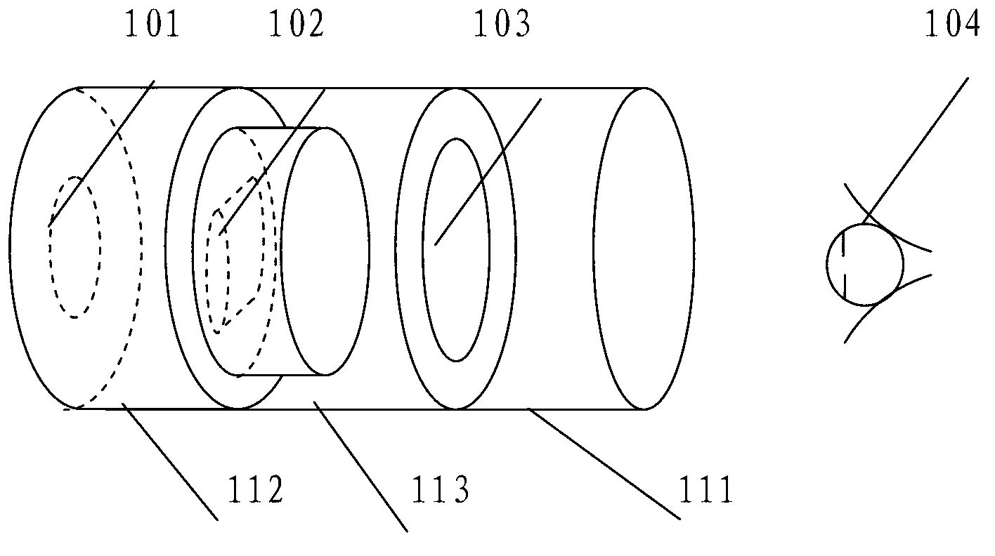
[0138] refer to figure 2 , shown as a specific example.

[0139] The lens 103 is fixed in the first sleeve 111 , and the front surface of the cornea of ​​the subject's eye 104 is located at the focal point of the lens 103 . The marker 101 can also be a picture, striped lines of different orientations, or radiation similar to a traditional astigmatism meter. Radiation is used as an example in the following description. The marker 101 is fixed on the second sleeve 112, and the second sleeve 112 can slide in the first sleeve 111, and the distance between the marker and the lens can be changed by adjusting the second sleeve 112. The cylindrical lens is fixed on the third sleeve 113, and the third sleeve 113 can slide in the second sleeve 112 and rotate with the sleeve shaft as the rotation axis. Adjusting the third sleeve 113 can change the orientation of the cylindrical lens and the cylindrical lens. The distance to the marker. When the second sleeve 112 is adjusted, the thi...


PUM


Abstract

The invention discloses a subjective optometry instrument which comprises an imaging lens and a marker, wherein the front surface of the cornea of a testee is located at a focal point of the imaging lens, the marker and the eye of the testee are respectively located on the two sides of the imaging lens along the optical axis of the imaging lens, the marker can move forward and backward along the optical axis of the imaging lens after being set, the subjective optometry instrument marks a value D1 used for distinguishing the spherical equivalent along the moving path of the marker, a moving position x is obtained by subtracting the focal distance f0 from the object distance of the marker, and when the eye of the testee sees clearly the marker, the spherical equivalent of glasses to be worn on the eyes of the testee is the corresponding spherical equivalent D1 at the moving position x of the marker. The invention further discloses a subjective optometry method. Different from the traditional scheme, the positions of an eye lens and the human eye are needed to be moved to implement refraction compensation in the traditional scheme, the optometry method and the optometry instrument are not required to move the human eye and the lens, but only the marker is moved. When the optometry instrument and the optometry method are adopted in optometry, simplicity and convenience can be achieved, and the cost is low.

Description

technical field [0001] The invention relates to human eye optometry technology, in particular to a subjective optometry instrument and optometry method. Background technique [0002] Use an eye chart to check your eyesight, which is to check the resolution ability of the eyes. Optometry checks the refractive state of the eye. Although these two different inspections are related to a certain extent, the purposes of the two inspections are different and cannot replace each other. The traditional eye chart is a simple and easy-to-operate equipment for testing human eyesight, and has been popularized in ordinary families. However, traditional optometry equipment has a complex structure, requires doctors to operate, and is expensive, so it is difficult to popularize in families and communities, let alone be used as a tool for self-examination. Contents of the invention [0003] The purpose of the present invention is to overcome the deficiencies of the prior art and provide ...

Claims


Application Information

Patent Timeline
Patent Type & Authority Applications(China)
IPC IPC(8): A61B3/028
CPCA61B3/028A61B3/0075A61B3/032
Inventor 郭曙光王辉李鹏朱晓湘吴蕾张德兴
Owner SHENZHEN CERTAINN TECH CO LTD
Learn More