Blank pipe fitting lateral surface punching die

A technology for empty pipe fittings and punching dies, applied in the field of side punching dies for empty pipe fittings, can solve the problems of side hole deformation, large side hole deformation, easy rupture of casing cores, etc. low cost effect

Inactive Publication Date: 2013-09-18
何祺晃
View PDF8 Cites 10 Cited by
  • Summary
  • Abstract
  • Description
  • Claims
  • Application Information

AI Technical Summary

Problems solved by technology

[0002] At present, there are two ways to process side holes on the side of empty pipes such as stainless steel pipes, iron pipes, copper pipes, etc.: one is the punching method with a casing core, that is, inserting the empty pipe into a hole that loosely fits the inner hole of the empty pipe. In the casing core, then use the punching core to punch and open the hole, wherein the casing core is provided with a punching hole that makes way for the punching core, and the punching hole is a through hole. This structure is only suitable for punching small holes whose maximum width is the cross-section size of the inner hole of the empty pipe minus 8mm. The side hole coming out is not tightly fit between the sleeve mold core and the inner hole of the empty pipe (if it is a tight fit, the shape of the empty pipe will be slightly deformed after punching after the empty pipe is placed on the sleeve mold, and the empty pipe will It will be difficult to pull out from the casing core, so a large gap needs to be reserved between the casing core and the inner wall of the empty pipe), and the processed side hole will be deformed; the other is punching without casing core Hole method, the side hole punched by this method has a large deformation, and is generally used to punch small holes and holes without requirements

Method used


Image

  • Blank pipe fitting lateral surface punching die
  • Blank pipe fitting lateral surface punching die
  • Blank pipe fitting lateral surface punching die

Examples


Embodiment Construction

[0020] The present invention will be described in further detail below in conjunction with the accompanying drawings and embodiments.

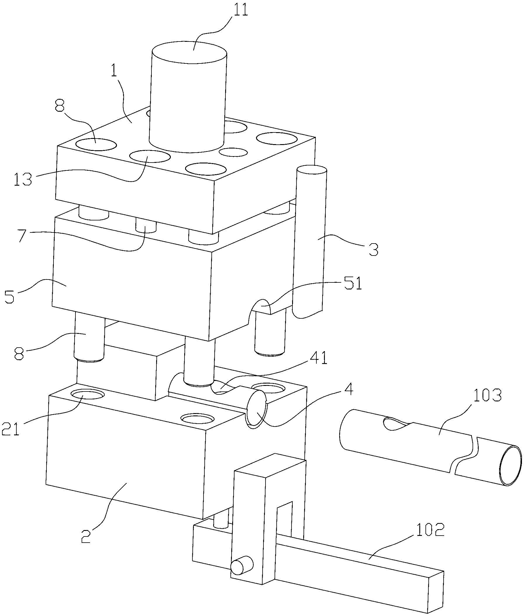
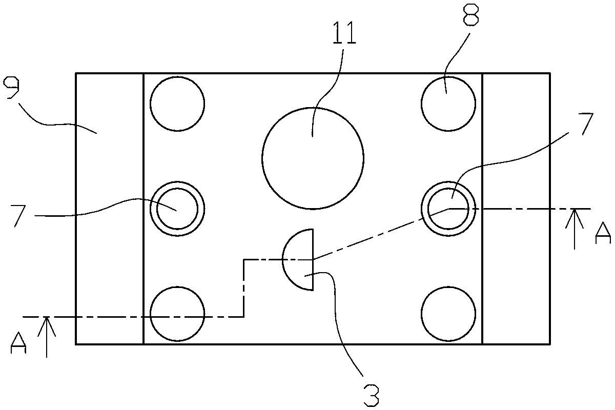
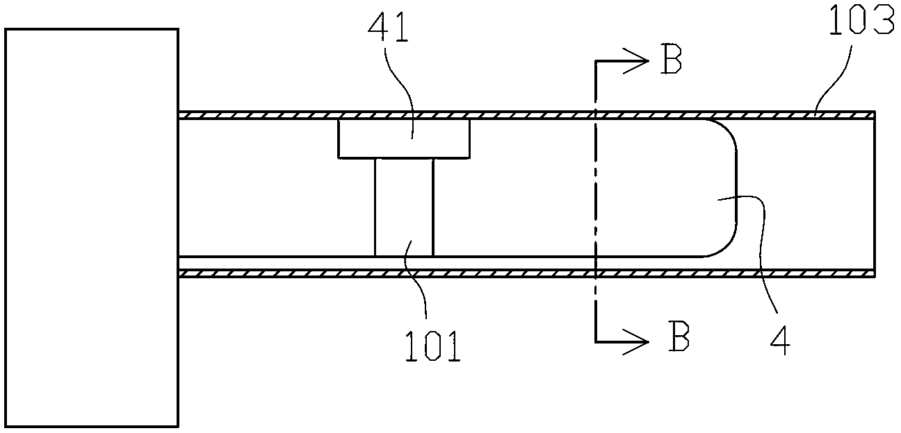
[0021] see Figure 1~Figure 7 , the hollow pipe side punching die of the present invention, it comprises upper mold 1 and lower mold 2, and the top of upper mold 1 is connected with mold handle 11 and is used for connecting and fixing with punching machine, and described upper mold 1 is fixedly connected with punching machine. Hole mold core 3, lower mold 2 is equipped with sleeve mold core 4 for sheathing empty pipe fittings 103, sleeve mold core 4 is provided with the punching hole 41 that gives way to described punching mold core 3, in punching At this time, the punching die core 3 breaks the cut part on the empty pipe fitting 103 and then extends into the punching hole 41, and also includes a movable pressure tube template 5, which is connected to the bottom of the upper die 1 end and can move up and down with the upper mold 1, the movabl...


PUM


Abstract

The invention discloses a blank pipe fitting lateral surface punching die and abandons the structure that in the prior art, a punched hole on a sleeve die core is a through hole and the sleeve die core is in loose fit with a blank pipe fitting. The inner walls of a sleeve die core and a blank pipe fitting are partially abutted against each other; the blank pipe fitting lateral surface punching die adapts to slight deformation of the blank pipe fitting in the punching process; and the blank pipe fitting lateral surface punching die is matched with a movable pressure pipe die plate and an elastic device, so that when a side hole is punched, the movable pressure pipe die plate descends to compress the blank pipe fitting and then an upper die continuously descends to squeeze the elastic device to enable a punching die core to slide downwards in a slideway on the movable pressure pipe die plate and efficiently compete the punching action. The punched big side hole of the blank pipe fitting is not deformed; in the punching process, the sleeve die core is difficult to break; the service life of each part of the punching die is prolonged; and the blank pipe fitting lateral surface punching die has the characteristics of high efficiency, no deformation, suitability for punching various sizes of side holes and the like.

Description

technical field [0001] The invention relates to a die, in particular to a side punching die for an empty pipe that punches out a hole close to the pipe diameter on the side of the empty pipe. Background technique [0002] At present, there are two ways to process side holes on the side of empty pipes such as stainless steel pipes, iron pipes, copper pipes, etc.: one is the punching method with a casing core, that is, inserting the empty pipe into a hole that loosely fits the inner hole of the empty pipe. In the casing core, then use the punching core to punch and open the hole, wherein the casing core is provided with a punching hole that makes way for the punching core, and the punching hole is a through hole. This structure is only suitable for punching small holes whose maximum width is the cross-section size of the inner hole of the empty pipe minus 8mm. The side hole coming out is not tightly fit between the sleeve mold core and the inner hole of the empty pipe (if it ...

Claims


Application Information

Patent Timeline
Patent Type & Authority Applications(China)
IPC IPC(8): B21D28/34B21D28/28
Inventor 何祺晃
Owner 何祺晃
Why Eureka
Try Eureka